Yes. I2S for an old tda1543 dac -- works fine (but that dac does not require MCK, just three I2s + gnd):Have you verified that your XMOS board works with some other DAC?
https://www.diyaudio.com/community/...-3-5-cd-player-schematics.395185/post-7267306
Are you clear on how this board can be made to meet your needs ?I have this "high-rated" adapter on order:
https://www.ebay.com/itm/274101835307
Made by XING Digital ???
I said this above - I use SN74LVC1G80, but any D-trigger with inverted output, which is able to work at that frequencies, can be used.Name the sot23 device and describe or provide a ckt.
Talk to me like I'm a student in a "101" class.
Sorry, didn't mean to abuse you.
But I can't understand why so many people discuss complex solutions, like XMOS/FPGA re-programing, instead of simple and obvious ones?
Alex.
As clear as I believe I can be based on the item's eBay description . Speaking of which, what I'm unclear about is why you, rfbrw, have selected only part of my orig post (52) to select-quote in your post (82).Are you clear on how this board can be made to meet your needs ?
https://www.diyaudio.com/community/threads/xmos-xu208-or-amanero-usb.323116/post-7271721
Please clarify.
Folks may want to read my entire post -- 52 -- which suggests that that particular device may be a solution:
I have this "high-rated" adapter on order:
https://www.ebay.com/itm/274101835307
Made by XING Digital ???
It's eBay product description does note: ". The MCLK output frequency can be individually configured for any format. From 64Fs to 512FS, from 2.8224MHZ to 49.152MHz, let the DAC chip exert excellent performance."
Hopefully this means a more straightforward solution.
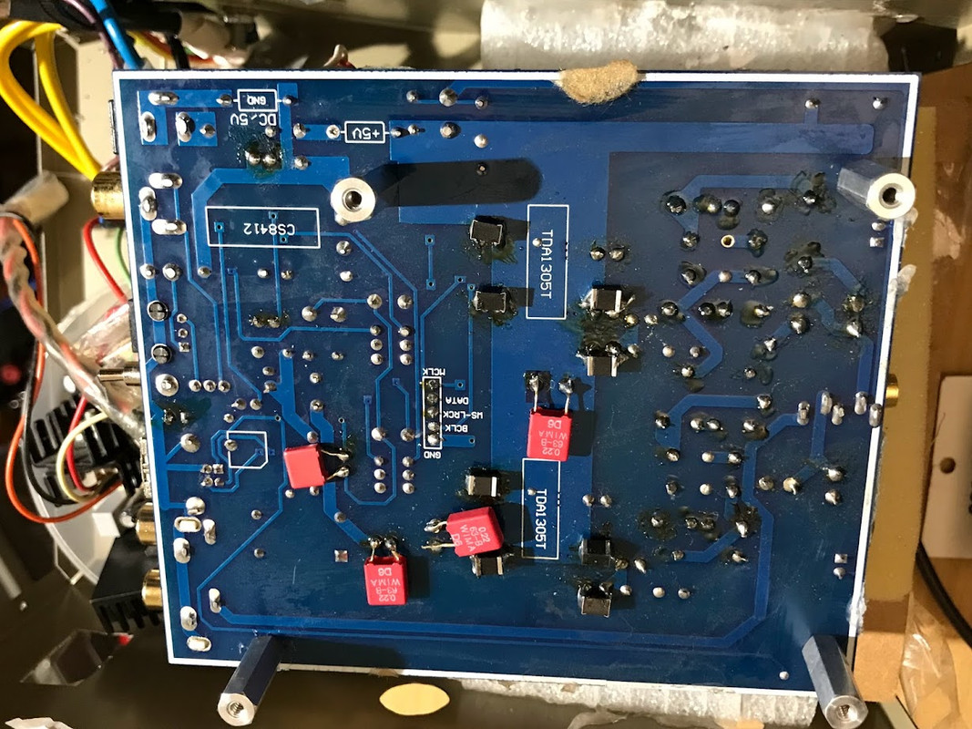
I just had a quick look at the TDA1305's datasheet.
It states: "I2S-bus with data word lengths of up to 20 bits (at fsys= 256fs)"
Are you sure that your XMOS is outputting 16 bits?
Some computers output constantly 32 bits, regardless of your source material.
It states: "I2S-bus with data word lengths of up to 20 bits (at fsys= 256fs)"
Are you sure that your XMOS is outputting 16 bits?
Some computers output constantly 32 bits, regardless of your source material.
And one more thing.
The TDA1305 is a 5V part, so it needs to see compatible voltage levels for MCLK & I2S signals.
This means that 3.3V will not cut it.
MCLK must be >4V and I2S > 3.5V.
The TDA1305 is a 5V part, so it needs to see compatible voltage levels for MCLK & I2S signals.
This means that 3.3V will not cut it.
MCLK must be >4V and I2S > 3.5V.
About 16 bit output. I assume yes , 16 bit, given that the XMOS adapter works with an old 8-pin tda1543 (which does not need MCK; see my prev posts on this).I just had a quick look at the TDA1305's datasheet.
It states: "I2S-bus with data word lengths of up to 20 bits (at fsys= 256fs)"
Are you sure that your XMOS is outputting 16 bits?
Some computers output constantly 32 bits, regardless of your source material. ====
And one more thing.
The TDA1305 is a 5V part, so it needs to see compatible voltage levels for MCLK & I2S signals.
This means that 3.3V will not cut it.
MCLK must be >4V and I2S > 3.5V.
==
About "The TDA1305 is a 5V part, so it needs to see compatible voltage levels for MCLK & I2S signals. .... MCLK must be >4V and I2S > 3.5V.":
There is nothing in the 1305's datasheet to suggest that as requirement afaics.
Look at the DS carefully. The 1305 can run on as little as 3.4v.
Also, I just see: fsys [mck] system clock frequency (pin 12). No voltage/current requirements.
And, as noted previously, usb adapter works fine with the tda1543 I2S lines.
Wasn't expecting the Spanish Inquisition but here goes.As clear as I believe I can be based on the item's eBay description . Speaking of which, what I'm unclear about is why you, rfbrw, have selected only part of my orig post (52) to select-quote in your post (82).
https://www.diyaudio.com/community/threads/xmos-xu208-or-amanero-usb.323116/post-7271721
Please clarify.
Folks may want to read my entire post -- 52 -- which suggests that that particular device may be a solution:
The Xing device claims much without the slightest indication as to how to achieve it which suggests to me that you may find yourself back where you started. I'd have gone for a real Amanero on the basis that there is a configuration tool on their website and an explicit statement about 256Fs operation but that's moot.
As to the Ebay/Ali stuff. You best ask them.
Re voltage levels see System clock input on page 10.
BTW for those in the peanut gallery below is the XS1-L1 usb audio board from XMOS.
The TDA1305 can run on as low as 3.4V, but what does your 1305 run on?About 16 bit output. I assume yes , 16 bit, given that the XMOS adapter works with an old 8-pin tda1543 (which does not need MCK; see my prev posts on this).
About "The TDA1305 is a 5V part, so it needs to see compatible voltage levels for MCLK & I2S signals. .... MCLK must be >4V and I2S > 3.5V.":
There is nothing in the 1305's datasheet to suggest that as requirement afaics.
Look at the DS carefully. The 1305 can run on as little as 3.4v.
Also, I just see: fsys [mck] system clock frequency (pin 12). No voltage/current requirements.
And, as noted previously, usb adapter works fine with the tda1543 I2S lines.
Because the acceptable levels for these lines depend on the actual Vdd the chip runs on:
If your 1305 is running on 5V, it will not function correctly with 3.3V logic (which in fact runs below 3.3V). It would explain your barely audible / heavily distorted audio.
Do not consider the 1543 to be the same as the 1305. They are very different devices / architectures.
TDA1305T datasheet does not specify the timing relationships between sysclk (MCK) and I2S signals so there is no apparent reason why divider by 2 on the XMOS MCK should not work. How do the I2S signals look at TDA1305 pins?
Thanks for everybody's feedback!
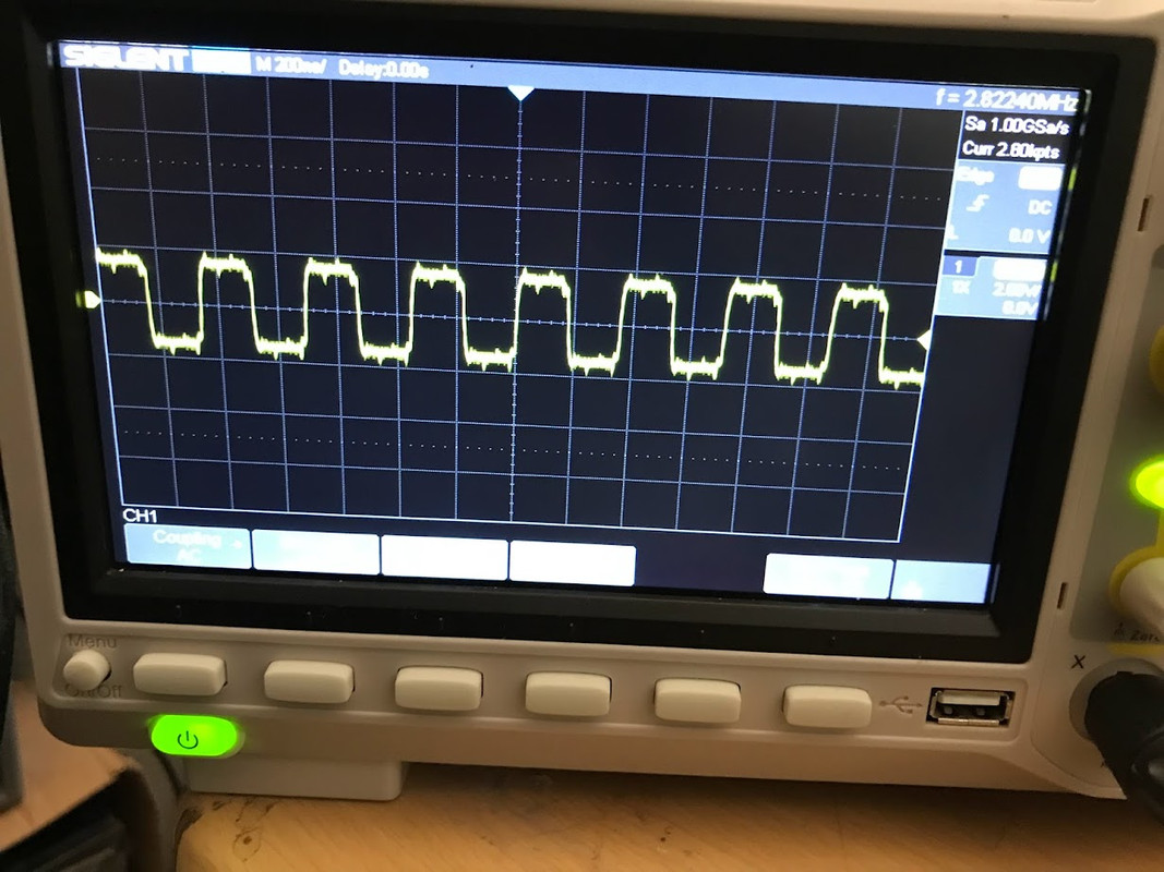
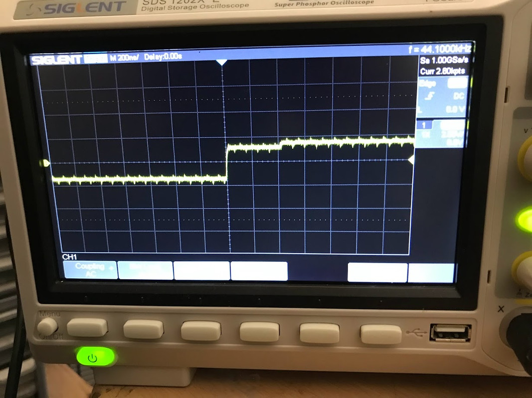
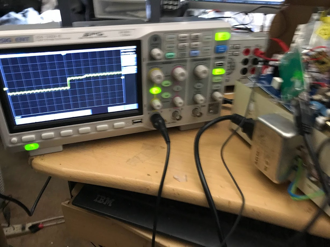
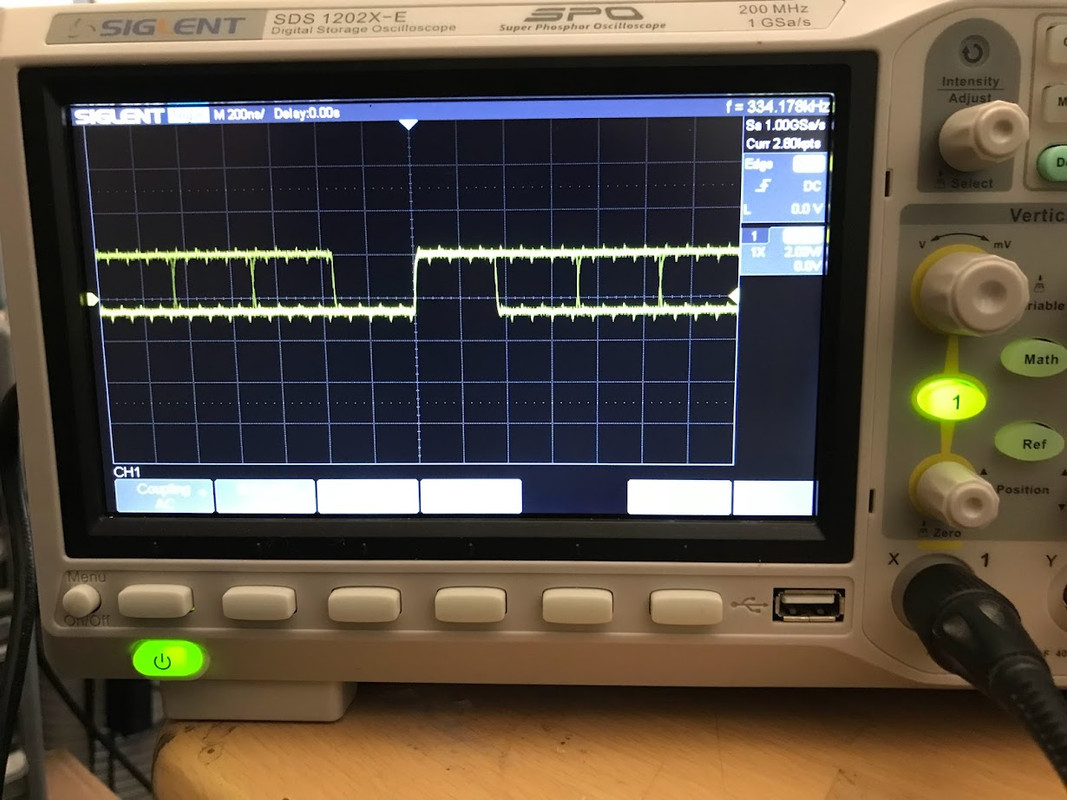
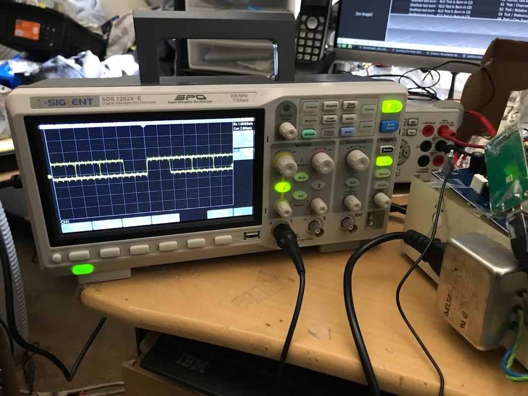
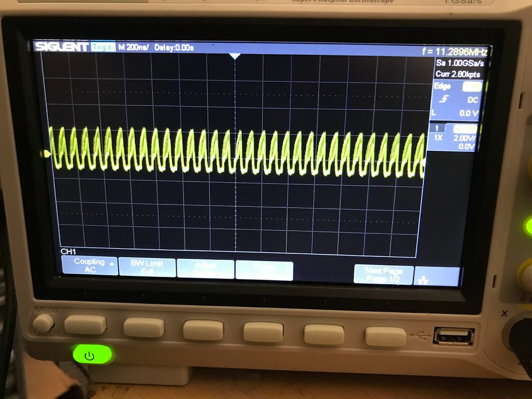
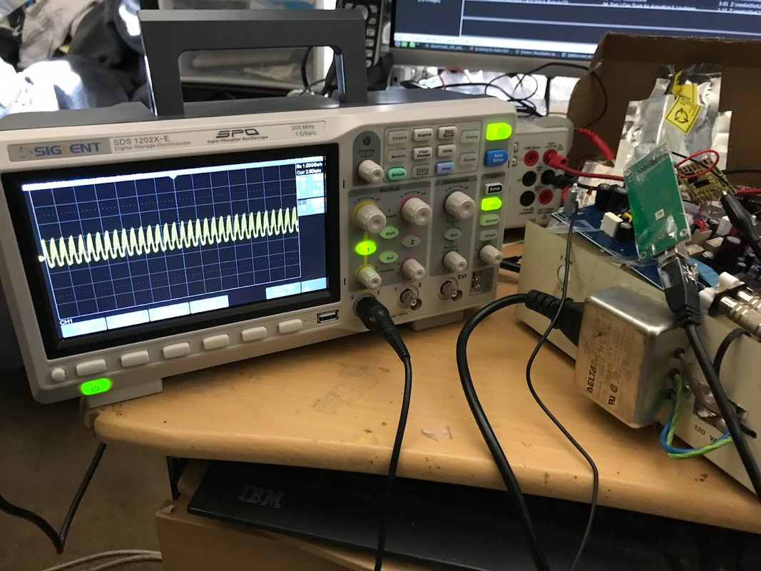
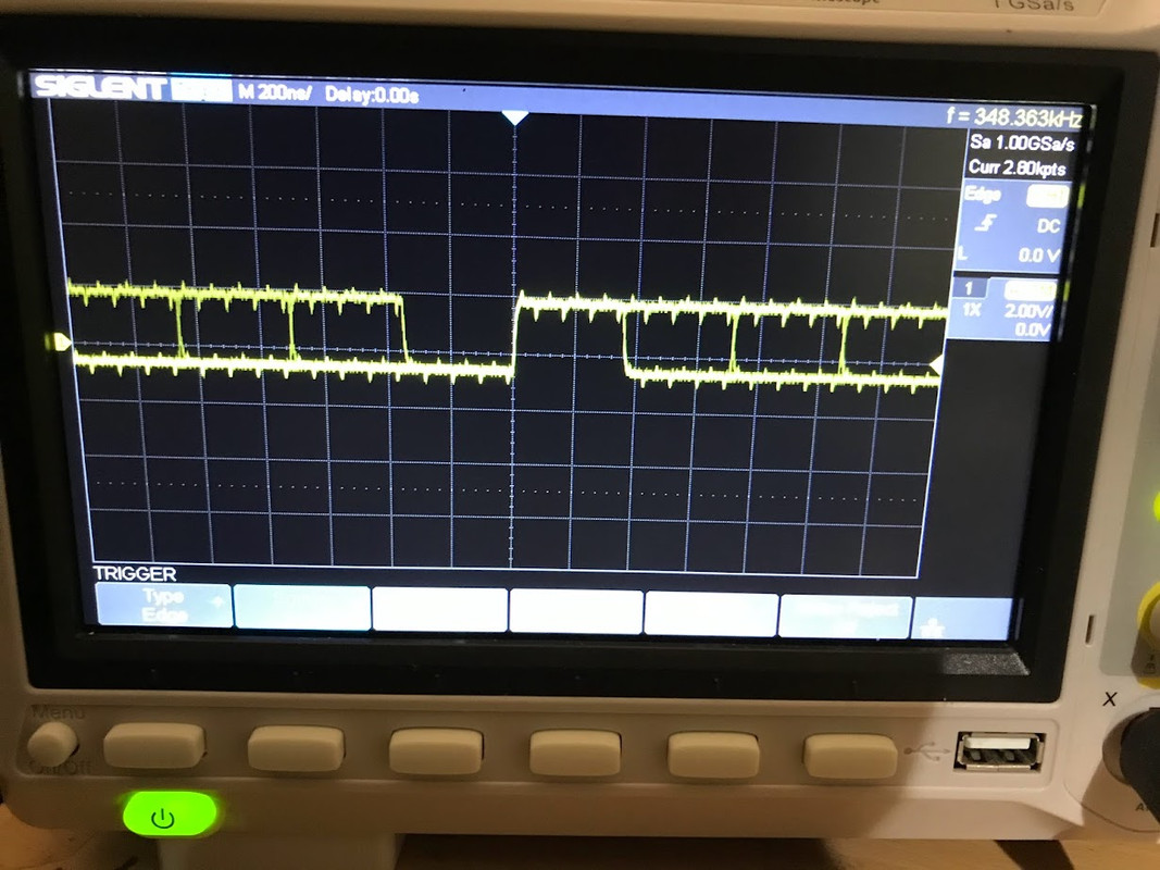
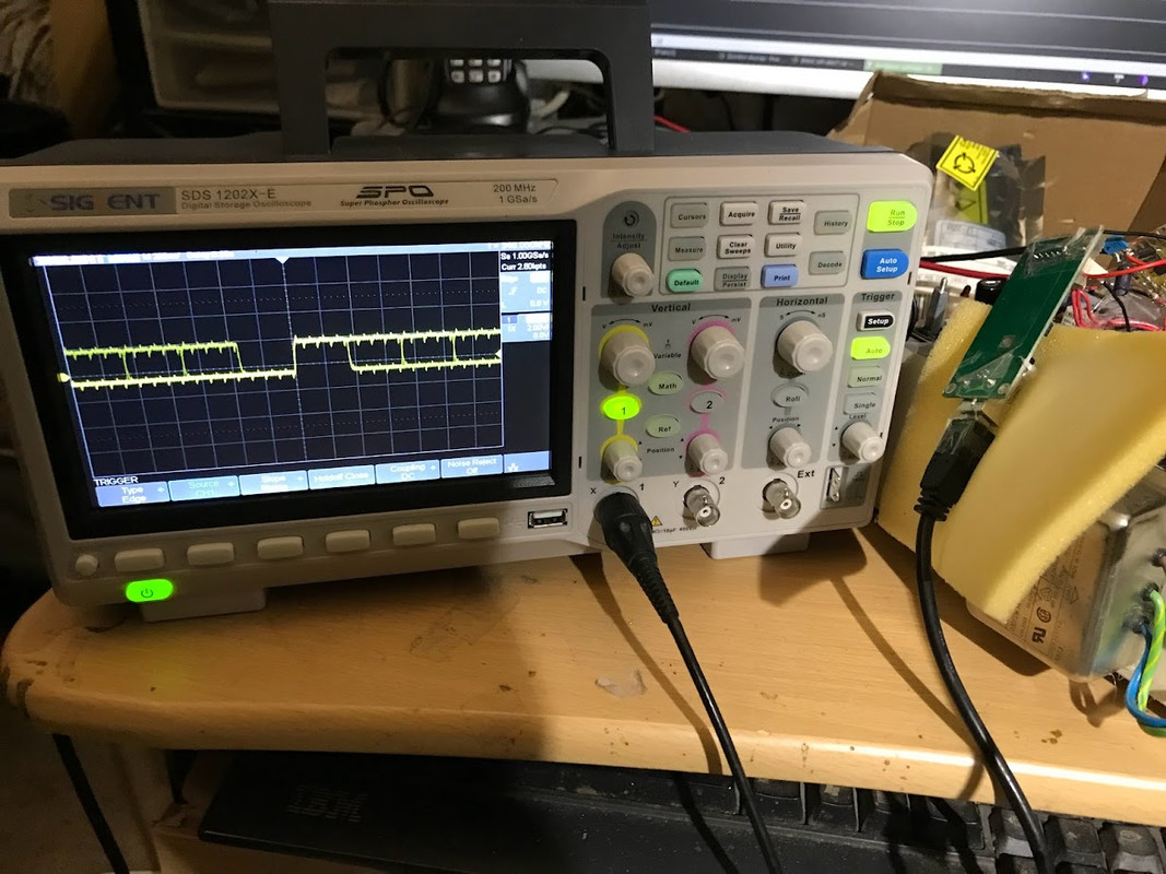
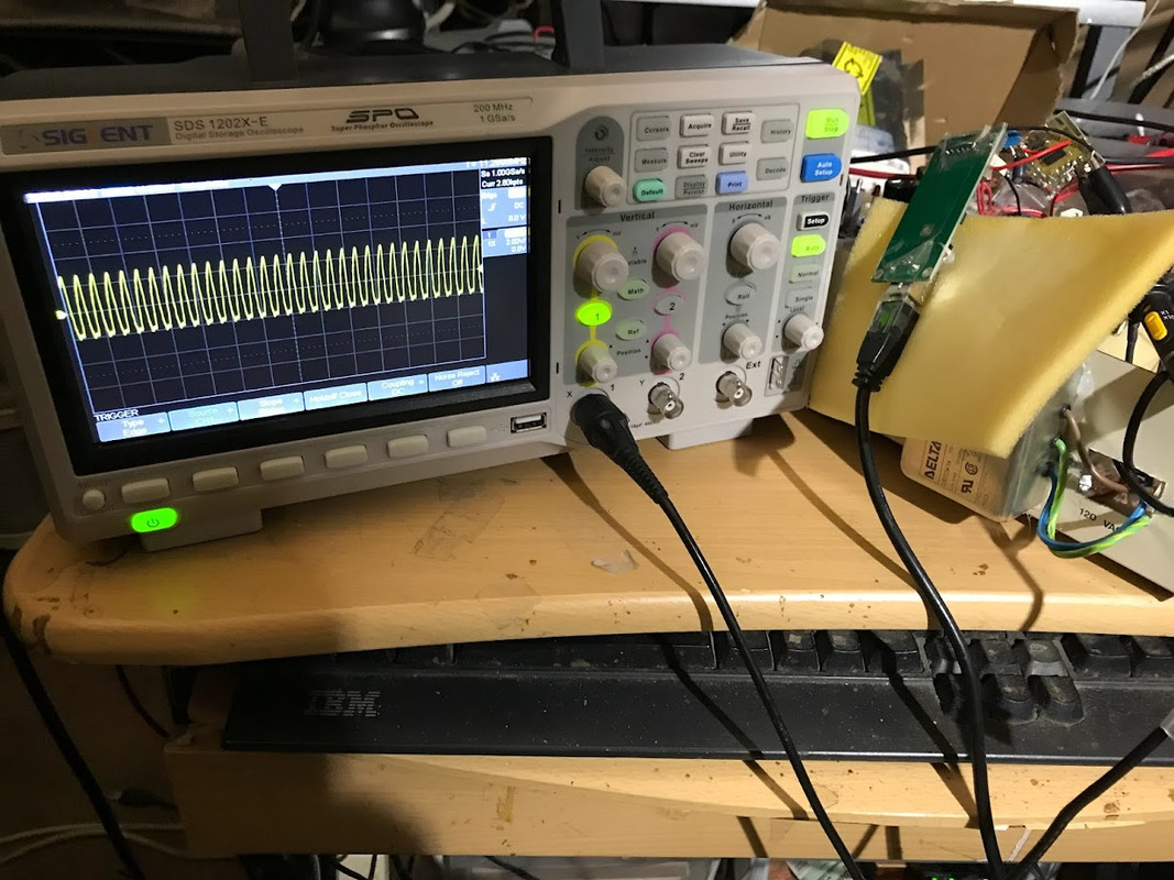
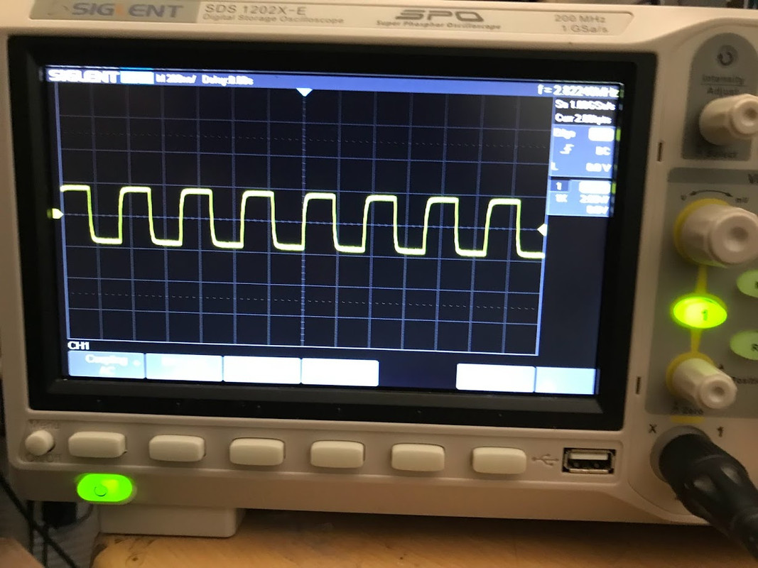
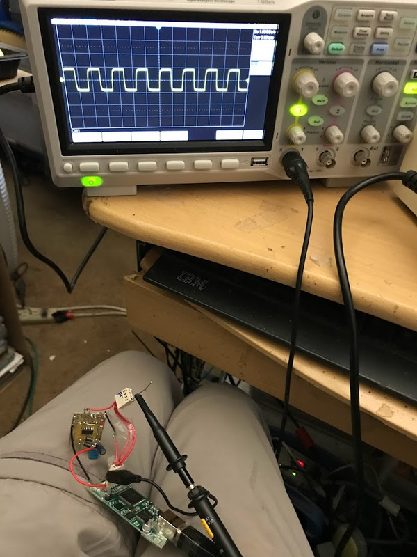
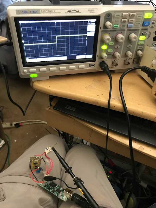
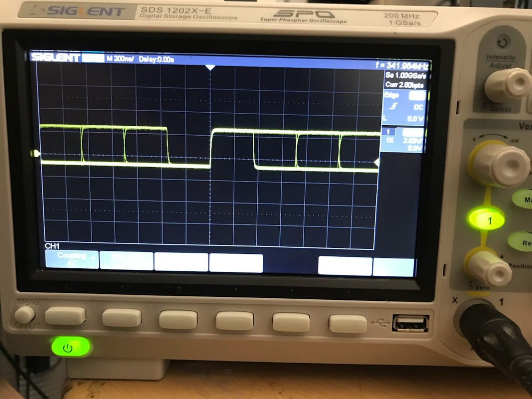
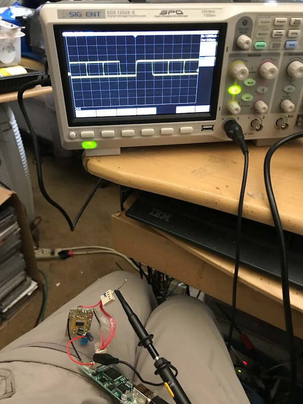
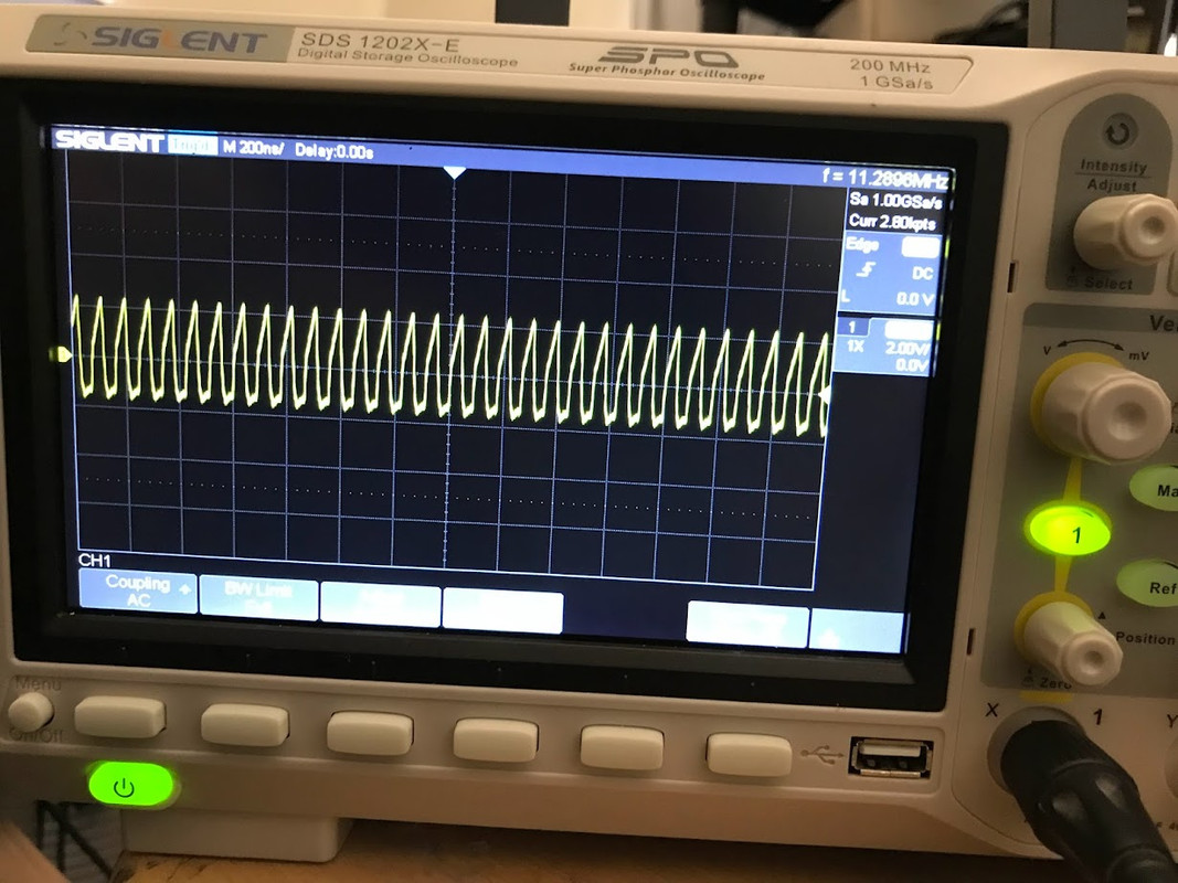
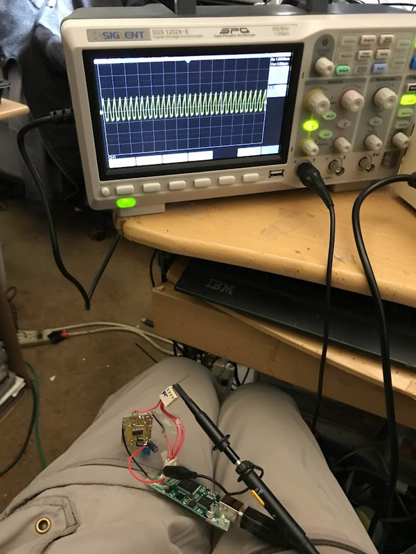
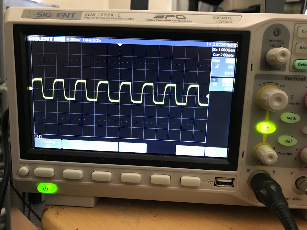
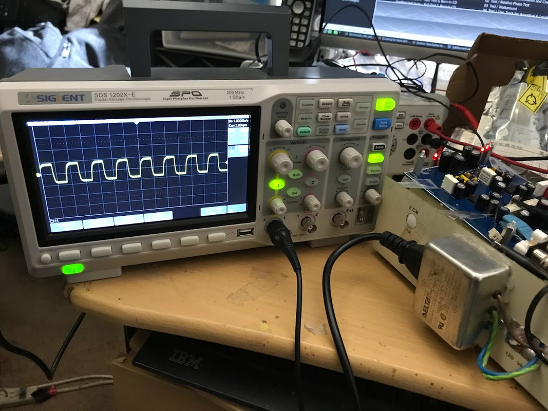
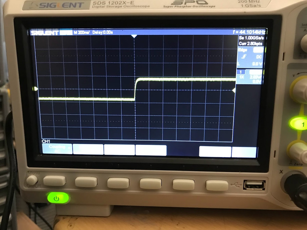
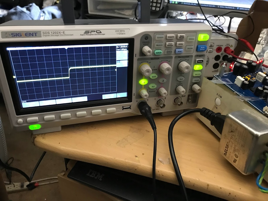
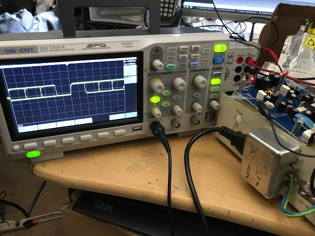
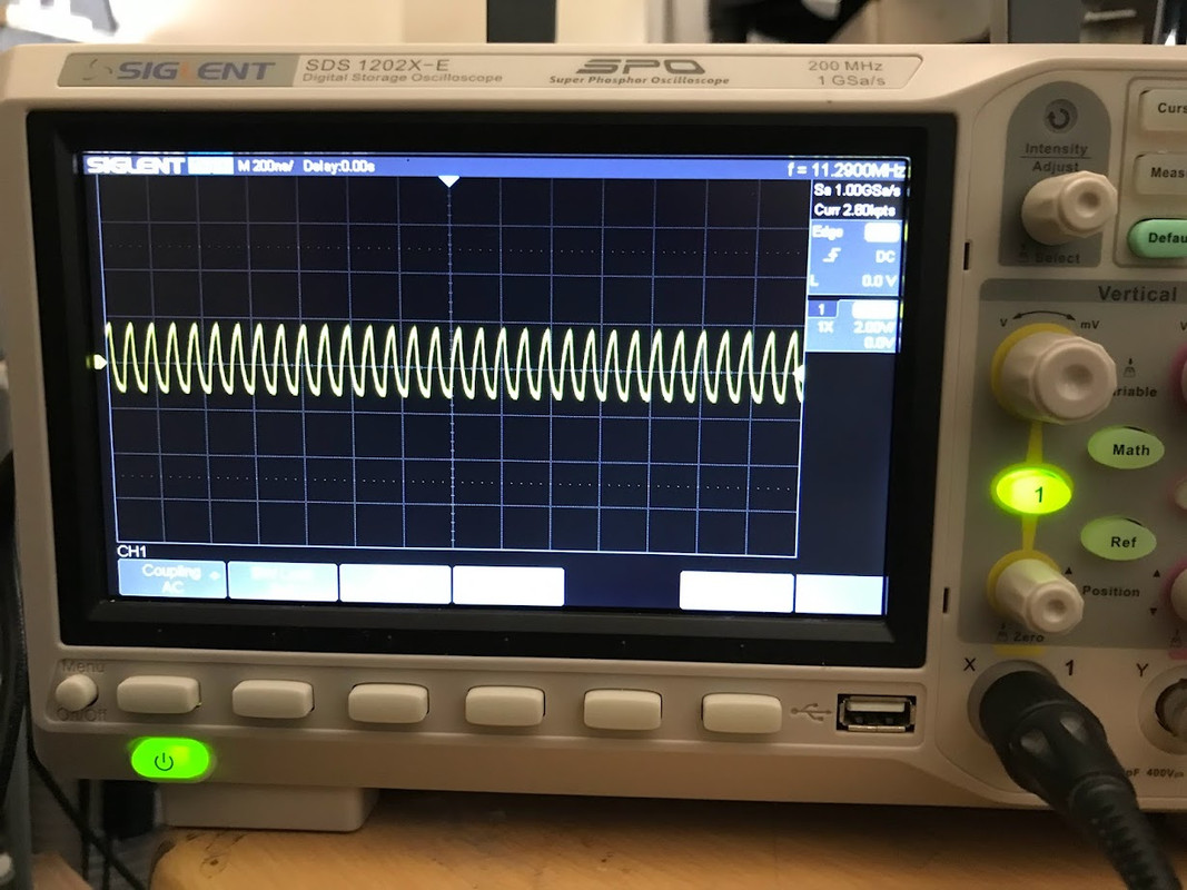
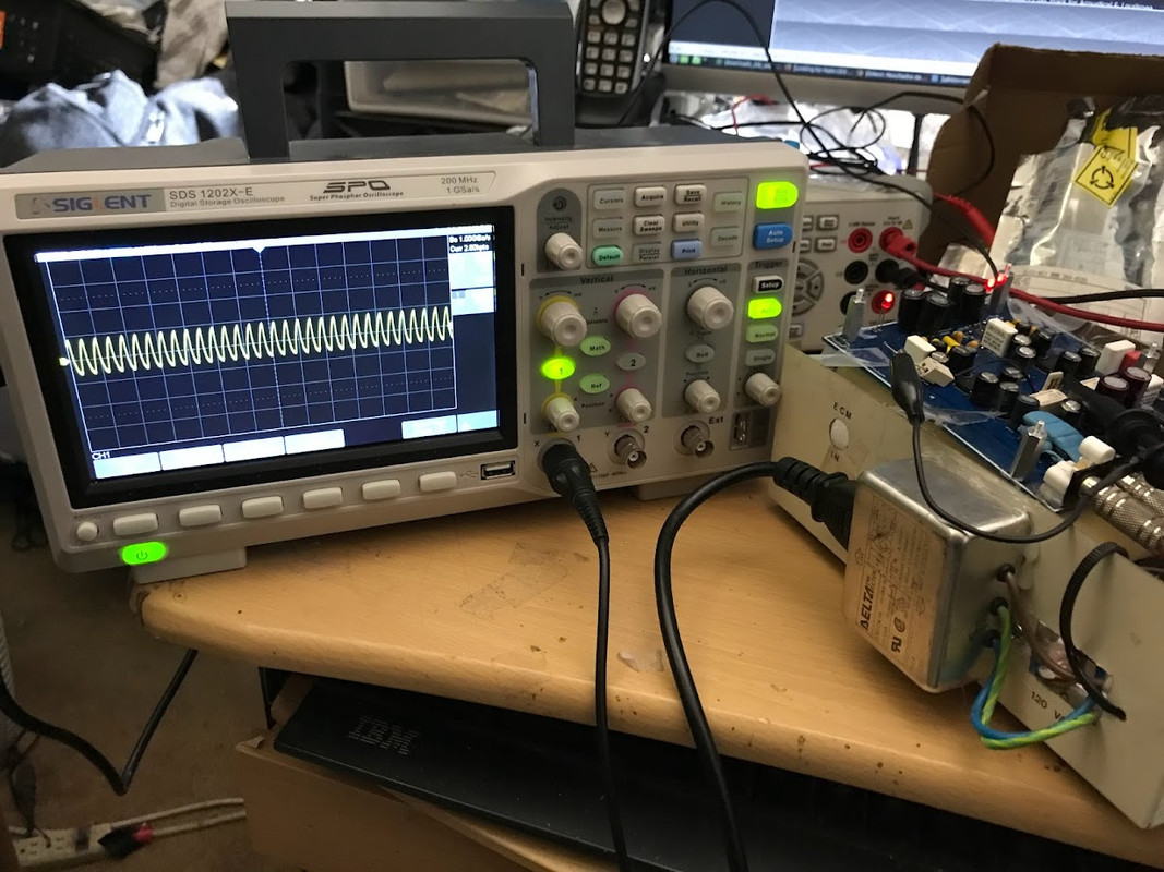
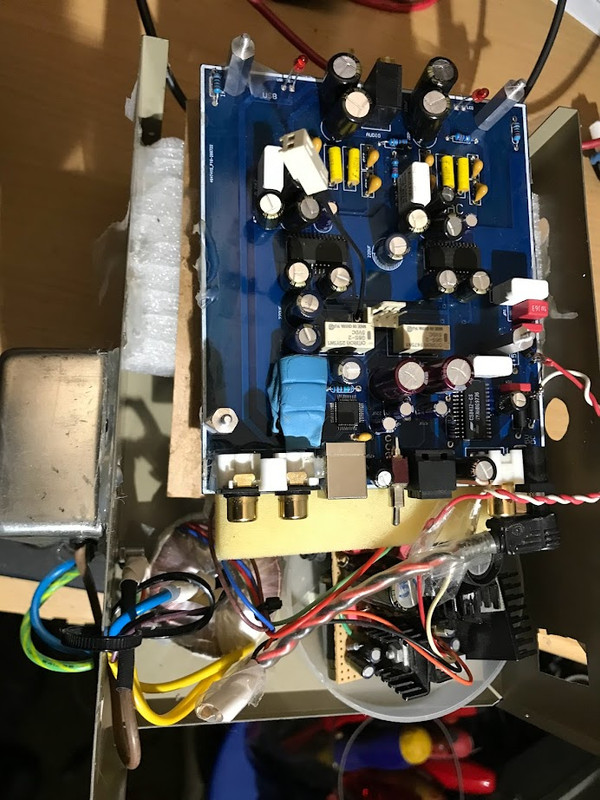
I'm going to photo bomb a bit, to show what I have encountered, probing I2S and MCK lines in various experimental configs. I kept all scope and probe settings the same (untouched) in all config setups -- which you can see from the photos.
For most captures, I show both a wide shot (scope + setup) as well as closeup of the scope screen.
USB cable connected to a diy "high-end" ultra-clean Linux PC playing 16/44.1 tone-signal files via Foobar.
BOTTOM LINE: Something about plugging in the XMOS adapter into the Chinese 1305 board (regardless of whether any/all sections of the Chinese 1305 pcb are powered) is adding noise (easily visible from scope) to three I2S lines. Some kind of synergistic effect -- reflection, signal bounce, etc??? Strangely, the MCK waveform, even with the hack-job /2 ckt, is the "cleanest" waveform, esp. with Chinese 1305 pcb totally unpowered!
===================
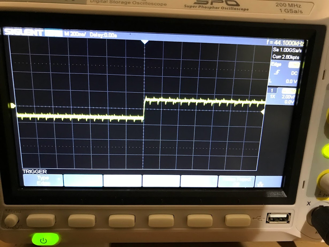
XMOS adapter connected to totally powered Chinese 1305 pcb (via Molex taps)

===================
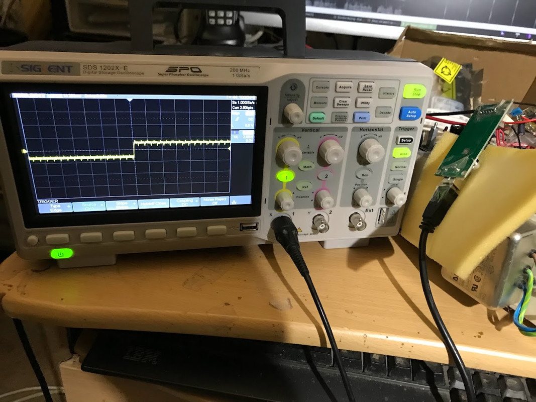
XMOS adapter connected to totally un-powered Chinese 1305 pcb (via Molex taps)
===================
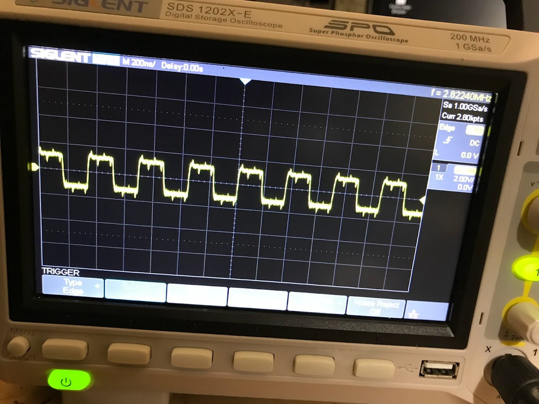
XMOS adapter connected to nothing

===============
Just the Chinese 1305 pcb, using its orig. stock USB input (no XMOS adapter in this setup) . Probing same I2S and MCK Molex taps on PCB.
====================
I'm going to photo bomb a bit, to show what I have encountered, probing I2S and MCK lines in various experimental configs. I kept all scope and probe settings the same (untouched) in all config setups -- which you can see from the photos.
For most captures, I show both a wide shot (scope + setup) as well as closeup of the scope screen.
USB cable connected to a diy "high-end" ultra-clean Linux PC playing 16/44.1 tone-signal files via Foobar.
BOTTOM LINE: Something about plugging in the XMOS adapter into the Chinese 1305 board (regardless of whether any/all sections of the Chinese 1305 pcb are powered) is adding noise (easily visible from scope) to three I2S lines. Some kind of synergistic effect -- reflection, signal bounce, etc??? Strangely, the MCK waveform, even with the hack-job /2 ckt, is the "cleanest" waveform, esp. with Chinese 1305 pcb totally unpowered!
===================
XMOS adapter connected to totally powered Chinese 1305 pcb (via Molex taps)
===================
XMOS adapter connected to totally un-powered Chinese 1305 pcb (via Molex taps)
===================
XMOS adapter connected to nothing
===============
Just the Chinese 1305 pcb, using its orig. stock USB input (no XMOS adapter in this setup) . Probing same I2S and MCK Molex taps on PCB.
====================
Last edited:
BTW for those in the peanut gallery below is the XS1-L1 usb audio board from XMOS.
This board is obsolete many years, and is not availiable now .
BTW, I have it.
To me it looks like the lines from the I2S connector are not properly terminated so you get huge reflections especially on MCK when TDA1305 board is powered. The lines seem to go through the relays but hard to say if removing them would help at all. My suggestion is to leave the board as is and forget about using the external USB-I2S board.BOTTOM LINE: Something about plugging in the XMOS adapter into the Chinese 1305 board (regardless of whether any/all sections of the Chinese 1305 pcb are powered) is adding noise (easily visible from scope) to three I2S lines. Some kind of synergistic effect -- reflection, signal bounce, etc??? Strangely, the MCK waveform, even with the hack-job /2 ckt, is the "cleanest" waveform, esp. with Chinese 1305 pcb totally unpowered!
Yeah, I posted on those Omron relays in the Naim 1305 thread. I'll have to trace them out soon. I did trace the MCK from the input pin of 1305 to the MCK pin on the CS8412. It is not going thru a relay -- a direct 0-ohm pcb trace.To me it looks like the lines from the I2S connector are not properly terminated so you get huge reflections especially on MCK when TDA1305 board is powered. The lines seem to go through the relays but hard to say if removing them would help at all. My suggestion is to leave the board as is and forget about using the external USB-I2S board.
More photos ... I added the Molex connector and ground Molex to thru-hole vias on the OEM board. Maybe they were put in by Chinese pranksters having a good LOL, at the expense of all us who fell for it ... 😏
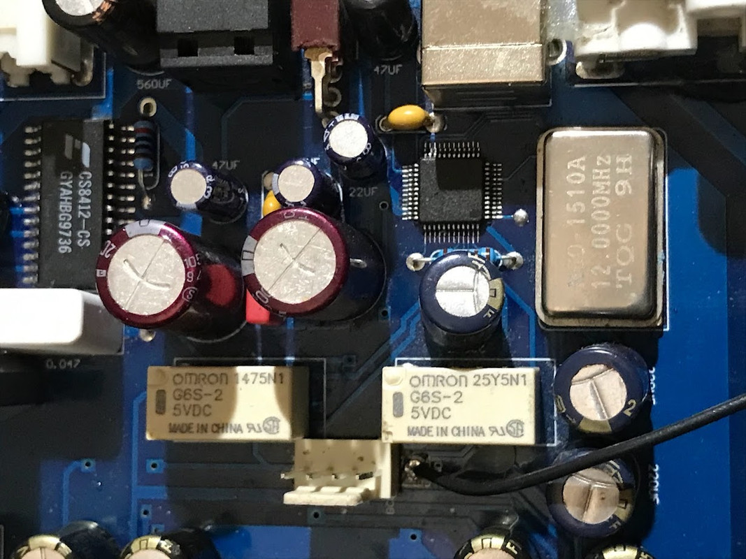
Small miniature or subminiature relays with gold or certain other precious metal contacts can be suitable for RF use, such as for dac clock signals. In particular, Omron makes some shielded RF relays in more or less the same format as their other SMD relays but that are specified in terms of s-parameters. Some example information they publish for certain relays: https://omronfs.omron.com/en_US/ecb/products/pdf/G6K-2F-RF-V_WhitePaper.pdf
Here is another type: https://omronfs.omron.com/en_US/ecb/products/pdf/en-g6k_2f_rf.pdf
However, such relays do need to be designed into an appropriately designed PCB with a ground plane. Also at some audio clock frequencies, selected non-RF rated relays can be used with very good results.
Only point being that relays are not necessarily a problem just because there are relays. If measuring, first thing is that the scope and probes need to suitable for clock pulse type measurements. Then transmission line termination optimization can be possible
Did you see my photo-bomb post from earlier today?If measuring, first thing is that the scope and probes need to suitable for clock pulse type measurements.
Something is too slow when the scope shot looks like this:
 I
I
The waveforms above do not look square enough to be plausible. The scope bandwidth is too low. Also, I can't read all the scope setting as well as would be ideal. Looks like there is a USB port on the front. A memory stick plugged in there should be able to accept a .bmp file or .jpg file of the scope display. Do you know how to save a file in maybe a .jpg = format you could post here?
The waveforms above do not look square enough to be plausible. The scope bandwidth is too low. Also, I can't read all the scope setting as well as would be ideal. Looks like there is a USB port on the front. A memory stick plugged in there should be able to accept a .bmp file or .jpg file of the scope display. Do you know how to save a file in maybe a .jpg = format you could post here?
The waveforms above do not look square enough to be plausible.
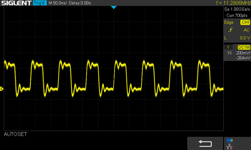
Perhaps, you are referring to the occurring phenomena? Yes, until recently, I overlooked it 😉
Last edited:

- Home
- Source & Line
- Digital Line Level
- XMOS XU208 Or Amanero USB