Hi Thermrcul,
I like your idea of rear mounted driver and bottom access panel. Great idea! The lack of bass has more to do with the volume and vent sizing than the aperture. I’m afraid you will need to redo the box if you want to continue to use the same driver. Or use it with support of a subwoofer located under your desk.
The trick to these plans is to always modify them to satisfy the internal dimensions no matter what the thickness of the material is. 30% reduction in volume can affect bass extension significantly. Use a bass reflex calculator and calculate ideal volume and vent size. Now drop that volume by 30% and see what happens to the bass.
You might look for a driver with same cutout but more powerful magnet for lower Qts. Look for Nd magnet drivers. Or Pro audio drivers like a faital pro 5FE100 or something like that.
Good luck!
Hi xrk,
Thanks for your reply.
Yes the design was modified correctly, but at assembly time I measured where the inner vent pieces should go incorrectly and thus have 30% less volume there now.
I only realised it after gluing it all together of course!
They still sound great, but needing 30db boost rather than 10db boost is disappointing. I don't think I have the heart to do a total rebuild and may just live with it, unless I can find a way to somehow undo the parts in the middle which have been glued together!
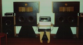
rear mounting was how KK-Audio, Acoustic Control, Transylvania Power, Westwood, and others built the X15 size bass cabinet.
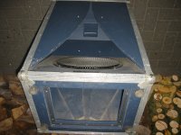
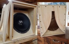
I think the one below was a "BEC2" by the late Ernst Beck under license from Transylvania Power. Although made of 18mm Russian birch plywood, it was necessary to brace the aperture's wings with 3/8" steel allthread bolts which run from the back through the port panel then through the wings to minimize modulation effects from wings' movement.
This cabinet's internal vent is much smaller than that of Acoustic's 115BK, whose vent was around 3 " high by 9 inches wide. I suspect tuning is simiilar
as the front chamber's aperture (being narrow at the top) has a major effect on system tuning.
These are excellent little cabinets to use in place of midbass horns.
Attachments
A question for X. Since the typical Karlson - style front chamber's volume tapers towards "zero" while the aperture width is approaching its maximum, can one assume with a bandpass box sim that only a certain portion of the front chamber is really "active"? (resulting in less front chamber size than with a box having a baffle parallel to its aperture/port)
Does your Akabak model have more refinement in this regard than a stock BP6 model?
Does your Akabak model have more refinement in this regard than a stock BP6 model?
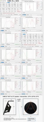
My Akabak model of a Karlsonator has a detailed K aperture profile that is accounted for. The XKi model is simplified and similar to a band pass sim you have. I can modify the K15 Akabak code to be an XKi and that would have the correct effect but I find it minor so don’t do it. It affects the midrange mostly.
I think the main thing is to give it room to breathe as a tight turn will increase effective port length.
quick question for XRK971 and other Karlsonites
How tight would you make the aperture's top gap and would you prefer it to start a little lower on this cubical XKi?
I guess it depends on how long an effective vent you want, as I think it will play on this, as well as BP6 tuning, as in the front load.
I had an alternative in my mind for venting the above mSK8 at the stub's apex, like your 12" Kube, but the aperture was not set in stone, it would have been a provision to tune the stub in this case.
I think I was on a similar path that led xrk971 to the XKi with that one.
What are the specs on that 12" Pyle?
hi X--tis not in my sweaty little hands yet---hoping it has some energy at 70Hz (?)
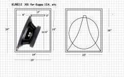
hi IG81 -- love that stub as it comprises a good chunk of the front chamber volume plus can null a cavity peak. Since you have brains and skill to make intelligible plans, might you sometime draw one for this KUBE12? It would be cool to have more K-ish plans and perhaps consolidate them from varoujs threads and the"compendium".
hi IG81 -- love that stub as it comprises a good chunk of the front chamber volume plus can null a cavity peak. Since you have brains and skill to make intelligible plans, might you sometime draw one for this KUBE12? It would be cool to have more K-ish plans and perhaps consolidate them from varoujs threads and the"compendium".
I don't think it's that critical on such a stubby kab, especially if you intend for it to be a woofer only. It looks about 1.5" wide to me.
Here's a little something I'm putting together for fun, as well as to have something different from my TK6, for purpose of comparative analysis.

I designed it as per the method described in the first post of this thread, for the Tang Band W4-1320SIF. I employed the Advanced Online Speaker Box Calculator to do the series BP6 design, using the T/S parameters I recently measured for them. Rear and front volumes are approximately 8L and 2L, which is a bit on the large side for this driver, but so is the DCR (6L + 3L) they`re currently in and doing well. I haven`t checked the simulation yet, but I'm fairly certain the Fostex FF125K (currently in the TK6) could do well in this XKi with little or no modification, as I regularly use them in a 8L reflex enclosures, albeit with an assumed ~2 Ohm of drive impedance. Both driver can also fit the 4" hole.
Construction is 0.5" MDF, much cheaper than BB-ply these days. The rear panel will be removable to allow the addition of a vertical vent panel if tuning corrections are required. I had to bevel the top cleats and vent panel edges to avoid restriction. The vent panel also has a longitudinal cleat bracing the top. External dimensions are about 12" high, 8" wide and 9" deep. It`s also my first time doing a "sideways assembly" for a Karlson. I would usually glue-up the sides, top and bottom and then install cleats and internal panels.
I have yet tot cut the wing panel and even to decide on the slot profile. I may start with a simple radial arc and will likely make a second set with a more open K-slot to compare.
I`ll follow-up with pictures as well as measurements.
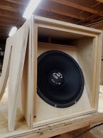
Some build progress. In fact, it's all done save for the aperture.


I will attempt a one-piece aperture panel, leaving a small strip of woof at the bottom. A radial arc of r=13.5" looks like a good fit for a standard K-slot, while r=27" will be good for a faster and more open profile.
I will attempt a one-piece aperture panel, leaving a small strip of woof at the bottom. A radial arc of r=13.5" looks like a good fit for a standard K-slot, while r=27" will be good for a faster and more open profile.
Finished one aperture. I made a bit of a notch in the r=13.5" panel and this one is supposed to be the r=27", but I think I messed up and re-used the same spacing hole on my jig because it looks the same. I'll take some measurements soon.

- Home
- Loudspeakers
- Full Range
- XKi - X's ab initio Karlson 6th Order Bandpass