During the development of diyF6 to now, I failed to grasp, and further appreciate the mechanism of action due to the so-called "pots" [e.g. P3 and P4 in post #94 above]. Is one deliberately tampering with the fidelity of the parent sine signal? By this I ask whether one strives to change the ratio of the area under the curve of the positive-going relative to the negative-going components of the sinusoid; which at the outset had both components identical [area, absolute amplitude]; or symmetric? Please elaborate. Thanks.
Here is my present understanding of the pots:
The pots make minor changes to the operating points of the JFETs. In a P-P configuration, the differences of the operating curves define the even harmonics. Think of each JFET drain current being a polynomial function of the input voltage. The each pot "tweaks" the the polynomial coefficients of the collection of pots in a different manner, resulting in 4 degrees of freedom in varying the harmonic structure.
This is the one thing i think most people miss when building an amp. THere are soooooo many variables that add up to a sound. NElson can post a schematic of an amp with parts numbers, but that is about as simple as it gets. From there, you could have any number of results, based soley on just the active parts used. In truth, an experimenters' board would have pots all over the place. Consider that when you see pots on a Pass amp, all other parts have been matched very well. How well, i dont know, but i would tend toward very well.
Here is my present understanding of the pots:
The pots make minor changes to the operating points of the JFETs. In a P-P configuration, the differences of the operating curves define the even harmonics. Think of each JFET drain current being a polynomial function of the input voltage. The each pot "tweaks" the the polynomial coefficients of the collection of pots in a different manner, resulting in 4 degrees of freedom in varying the harmonic structure.
assuming fairly well matched parts on all parameters. With SS fets, i think we were introduced to some unusual ones, like gate current. How many folks match the fets just for Vgs at one point and do no match for Cis? If your gonna do it right, its going to take a lot of effort. Burnt me out, fo show.
The only pots visible on the input board are in the vicinity of the JFETs, rather than the cascode transistors, making it unlikely that any of the four pots are related with JFET drain loading.
I see 4 pots on pics and not only 2 like in your schematic.
These pots are close to cascodes, VAS-mosfets, 2+2 resistors each 100R (?) and not to JFETs.
May be these pots vary collector resistors of cascodes, therefore influencing gain of input stage and also bias current in VAS.
Here is my present understanding of the pots:
The pots make minor changes to the operating points of the JFETs. In a P-P configuration, the differences of the operating curves define the even harmonics. Think of each JFET drain current being a polynomial function of the input voltage. The each pot "tweaks" the the polynomial coefficients of the collection of pots in a different manner, resulting in 4 degrees of freedom in varying the harmonic structure.
Thanks lhquam for your explanation; which makes full sense. Drain current of JFET [Id] and the input signal to its gate [Vi] are related by and/or give a value for its transconductance [Id/Vi]; which per your answer is not a constant. Per Mr. Pass, distortion [ H2, Hn etc] emanates inside a device when its gain [for example; transconductance] varies during the variation of current passing through it, and simultaneously during the variation of voltage across its terminals. This behavior of the device is totally normal.
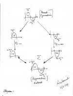
I am using the graphic in the attached image to ask whether it is conceptually a mechanism like the one generating such a distortion.
1. Start with a sinewave signal of a certain frequency. Its positive and negative-going components are also characterized by an identical area inside each of their curves [a], and by an identical peak amplitude [Vp] for each component. The parent signal is symmetrical
2. Make believe that I have the means to cleanly separate the positive from the negative component to generate DC pulses which continue to bear the identical characteristics of the components in the parent sinusoid.
3. Make believe that I am able to amplify one pulse more or less than the other [Vg = n or m where integer n is not equal to m]. This is the relevant connection of selective modification of transconductance for one pulse only and not the other.
4. Make believe that I am able to splice [cleanly] the resultant pulses and reconstitute an amplified output replica of the input signal which is now asymmetric by choice. Or the output signal is distorted.
This informal description is a mechanism by which I introduced a deliberate asymmetry [distortion] in the output signal. It is experimentally [and readily] doable to any extent of asymmetry [minor or major] for either the positive or the negative component of the output signal.
Attachments
The Pass Labs XA.8 series is a truly elegant design. Having studied the XA.8 specs and exploring a plausible schematic for the XA30.8 I now realize that nothing really changes to obtain the higher power versions other than the power supply voltages and wattages, the heat sink capacity, and a few changes to resistor values. The same number and type of output FETs can be used for the entire range. At 30W/ch, each output FET dissipates about 7.5W and at 200W/ch each output FET dissipates about 30W. Beautiful! 🙂
one thing is pretty certain - different XA*.8 amps are having different front stage(s) , regarding important resistor values
due to heavily reduced amount of NFB , different voltage output levels are dictating that
so ...... Jazz , Babe
due to heavily reduced amount of NFB , different voltage output levels are dictating that
so ...... Jazz , Babe
What is so different about the XA.8 series is that the highest power (200W/ch) version defines everything, and the smaller versions are just scaled down in power supply, heatsinks, and packaging while retaining the same output FETs. I have never seen this approach before.
In the F5-Turbo and Burning Amp series, higher power versions required more output FETs as well as higher voltages and larger heatsinks. The additional output FETs has more of an impact at higher frequencies due to the additional capacitance of their gates.
In the F5-Turbo and Burning Amp series, higher power versions required more output FETs as well as higher voltages and larger heatsinks. The additional output FETs has more of an impact at higher frequencies due to the additional capacitance of their gates.
Don't go balanced. Once you do, you never go back. About to pair Satori with 10" woofer for Pass SR2 style speaker. The Satori would reward building this amp.
The reviewers of the amp [via the Pass Labs web page] did an astounding description of its great performance; both objective [inclusive its specs by Pass] and subjective.
I remember the older days of the magazines like Radio-Electronics, Audio, and Stereophile, when Len Feldmann and others included a schematic of the amp; detailed or rudimentary, to go along with the review. I looked forward to each monthly magazine copy for these schematics; because they pictorially differentiated among the plethora of new and improved designs, and also declared in writing the ingenious thoughts of their amp designers. It is clear to me now that the schematics of the great-sounding XA series amps are guarded; much like a precious metal; because they are the ongoing bread and butter of Pass Labs.
I remember the older days of the magazines like Radio-Electronics, Audio, and Stereophile, when Len Feldmann and others included a schematic of the amp; detailed or rudimentary, to go along with the review. I looked forward to each monthly magazine copy for these schematics; because they pictorially differentiated among the plethora of new and improved designs, and also declared in writing the ingenious thoughts of their amp designers. It is clear to me now that the schematics of the great-sounding XA series amps are guarded; much like a precious metal; because they are the ongoing bread and butter of Pass Labs.
Last edited:
Hi ZM, but balanced amp do not like low ohm speakers do they? Imagine if they do, the output at 2 ohm load theoratically would be insane! Or 1 ohm?! 😛use manly speakers , you'll never go balanced
just too much power

On the face of it, I would have expected that you could, and I have played
with several approaches which manipulate the harmonic character in the
front end, but none of them subjectively duplicate having that character in
the output stage itself.
I don't have a good answer why, but I believe it relates to the manner in
which the output stage interacts with a complex load.
😎
How sensitive is the sound of an XA.8 to the choice of speakers, i.e. the complex load?
With multiple pairs, Class A bias, and plenty of current headroom, I cannot imagine it caring about the load unless unusually underpowered for the situation.
How sensitive is the sound of an XA.8 to the choice of speakers, i.e. the complex load?
To answer the question, not very sensitive. But this does give me an
excuse to describe some of our testing.
The Tannoy 15 HPD'S are the one common loudspeaker we listen to
(besides our own fine product) and it is an easy and efficient load. We do
this because it is particularly revealing of some of the artifacts we have an
interest in.
Unfortunately this doesn't allow proper testing into some of the tougher
loads out there, and hauling big heavy speakers in and out of multiple
locations is tedious and expensive.
We still do that too, but I also put together a passive network that drops
the sensitivity by 12 dB and/or makes the amp work into reactance that
dips to 2 ohms at several frequencies (I used a well known loudspeaker
as the model for that).
This allows us to still use the familiar Tannoys, but under conditions which
are appropriate to the bigger amplifiers.
One thing about it is that the ratios of harmonics are partially a function of
power level, and so we necessarily think in terms of a fraction of the rated
power which is appropriate for each amplifier. To some extent when we are
making adjustments, we work to duplicate the sound at that level.
😎
Understanding the XA.8 PP-SE Hybrid output stage
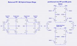
I have been thinking about the XA.8 output stage and have arrived at a way to better understand how it might work. The first figure is a possible (simplified) schematic of the XA30.8 output stage. The send figure is an abstraction of that schematic and its decomposition into balanced push-pull stages in parallel with bridged anti-phase single-ended stages.
With this decomposition it is very easy to understand the H2 and H3 of the each part. Assuming the pp-out+ and pp-out- parts of the balanced push-pull stage are identical, then the equal H2 outputs subtract and are totally nulled and the equal H3 outputs add. The anti-phase H2 and H3 outputs add.
Thus the total output into the load is determined as:
BTW: The above generalizes to all even and odd harmonics.
I have been thinking about the XA.8 output stage and have arrived at a way to better understand how it might work. The first figure is a possible (simplified) schematic of the XA30.8 output stage. The send figure is an abstraction of that schematic and its decomposition into balanced push-pull stages in parallel with bridged anti-phase single-ended stages.
With this decomposition it is very easy to understand the H2 and H3 of the each part. Assuming the pp-out+ and pp-out- parts of the balanced push-pull stage are identical, then the equal H2 outputs subtract and are totally nulled and the equal H3 outputs add. The anti-phase H2 and H3 outputs add.
Thus the total output into the load is determined as:
- H1 = 2*H1(PP) + H1(SE+) + H1(SE-)
- H2 = H2(SE+) + H2(SE-)
- H3 = 2*H3(PP) + H3(SE+) + H3(SE-)
BTW: The above generalizes to all even and odd harmonics.
Attachments
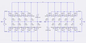
I have been thinking about the XA.8 output stage and have arrived at a way to better understand how it might work. The first figure is a possible (simplified) schematic of the XA30.8 output stage. The send figure is an abstraction of that schematic and its decomposition into balanced push-pull stages in parallel with bridged anti-phase single-ended stages.
With this decomposition it is very easy to understand the H2 and H3 of the each part. Assuming the pp-out+ and pp-out- parts of the balanced push-pull stage are identical, then the equal H2 outputs subtract and are totally nulled and the equal H3 outputs add. The anti-phase H2 and H3 outputs add.
Thus the total output into the load is determined as:
Formulas for these harmonics as a function of the FET KP parameter, the idle currents, and the source resistors (Rs) are forthcoming.
- H1 = 2*H1(PP) + H1(SE+) + H1(SE-)
- H2 = H2(SE+) + H2(SE-)
- H3 = 2*H3(PP) + H3(SE+) + H3(SE-)
BTW: The above generalizes to all even and odd harmonics.
Interesting schematics and analyses. What is the minimum % contribution of current by each of the lone SE Mosfets [left schematic of your post] to make a perceptible dent in the subjective sonics?
Best regards
- Status
- Not open for further replies.
- Home
- Amplifiers
- Pass Labs
- XA.8 single-ended current sources