The attached schematic was presented by lhquam in his post #119. It tells this fascinating story:
...
I wish the issue was as easy as that, but the all 5 FETs on the negative rail are contributing to both the PP and SE behavior as soon as the tops of their source resistors are tied together. However, it is possible to characterize the H2/H3 ratio as a function of:
- FET device characteristics, primarily Kp and lambda.
- Source (degeneration) resistance Rs
- Number of PFETs and NFETs
- Bias currents
- SE constant current
Story Part C
Hello lhquam. Wishful thinking on my part. You have a basis for an interesting and great diyamp. It lends itself to ready experimentation to go along with your simulation; for example by using a dual diyF4 per your post #82. Also, the potential standalone diy "balanced SE amp' in your schematic is already a unique achievement.
In conclusion to my story, a target H2/H3 for this study by lhquam may be like that already determined for diyF6. I've read diyF6 posts by lhquam, generg, Zen Mod, buzzforb, and countless others who have already spent many hours tweaking H2/H3, and may have to continue doing just so for this diyamp using 1K or more hours per posts #71 and 72 by Zen Mod, and generg respectively.
Best regards.
I wish the issue was as easy as that, but the all 5 FETs on the negative rail are contributing to both the PP and SE behavior as soon as the tops of their source resistors are tied together. However, it is possible to characterize the H2/H3 ratio as a function of:
The equations are not simple, and are quite difficult to express in closed form. However, the circuit is very simple to describe to SPICE for simulation, assuming you have suitable FET models.
- FET device characteristics, primarily Kp and lambda.
- Source (degeneration) resistance Rs
- Number of PFETs and NFETs
- Bias currents
- SE constant current
Hello lhquam. Wishful thinking on my part. You have a basis for an interesting and great diyamp. It lends itself to ready experimentation to go along with your simulation; for example by using a dual diyF4 per your post #82. Also, the potential standalone diy "balanced SE amp' in your schematic is already a unique achievement.
In conclusion to my story, a target H2/H3 for this study by lhquam may be like that already determined for diyF6. I've read diyF6 posts by lhquam, generg, Zen Mod, buzzforb, and countless others who have already spent many hours tweaking H2/H3, and may have to continue doing just so for this diyamp using 1K or more hours per posts #71 and 72 by Zen Mod, and generg respectively.
Best regards.
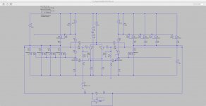
A different angle..
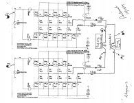
One thing led to another. This maybe a potential approach to manage H2 and H3 plus their magical ratio. The image shows the balanced mixed PP-SE amp which lhquam described; like that depicted in his post#119. There is one important modification therein this schematic to note. The electrical connection between the output of PP was disconnected from that of SE in the top and bottom sub-unit amps. This gives two independent power outputs; a balanced solo PP and a balanced solo SE.
1. The balanced solo PP output [Pout] is connected to Loudspeaker 1 and is enriched with an inherent H3 harmonic of a certain preferred magnitude. H3 may be determined at this Loudspeaker 1.
2. The balanced solo SE output [P'out] is connected to Loudspeaker 2 and is enriched with an inherent H2 harmonic of a certain preferred magnitude. H2 may be determined at this Loudspeaker 2.
3 The magnitude of Pout of balanced PP is greater than P'out of balanced SE; because of the particular [depicted] design of the individual PP and SE amps.
4. Loudspeakers 1 and 2 are independent, matched and are spatial mirror images.
5. Music emanates from each loudspeaker, and mixes the preferred levels of H2 and H3 harmonics [acoustically] in transit to the ears of the listener.
The next post shows Loudspeakers 1 and 2.
Attachments

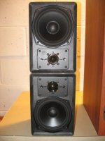
Loudspeakers 1 and 2.
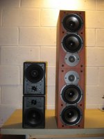
A closeup of an example Loudspeakers 1 and 2 is shown in the left photo. The two A/D/S L300C loudspeakers are independently enclosed, preferably matched in performance, and are positioned on top of each other to be mirror images in the horizontal plane. The right photo is another example showing a pair of Polk Monitor 4B loudspeakers [at hand] next to the pair of L300Cs.
Best regards.
Attachments
Now that's DIY
A paper exercise to a viable DIY which I formulated from valuable and reliable info in this thread. Load resistors to power amps are mute and speechless loudspeakers. Might as well use real deal loudspeaker loads for assessment/tweaking; like for example the practice of Mr. Pass with Tanoys.
One more post coming up.
On the face of it, I would have expected that you could, and I have played
with several approaches which manipulate the harmonic character in the
front end, but none of them subjectively duplicate having that character in
the output stage itself.
I don't have a good answer why, but I believe it relates to the manner in
which the output stage interacts with a complex load.
😎
How apparent is the sonic difference between an XA.8 and an XA.5 of the same power? Would the difference be apparent to a discriminating listener with decent speakers and listening room? I am trying to understand if the "manipulation" of the harmonic character in the output stage vs. the front end is something that many listeners would be able to differentiate.
There are many degrees of freedom in manipulating H2 vs. H3. One could null the H2 of the Front-End differential output, but with FEout+ and FEout- having relatively high levels of H2 that cancel. Alternatively one could null FEout+ and FEout- H2 by tweaking the JFET source resistors via the F5 P3 adjustment. How can a DIYer navigate the many alternatives? One could choose the option of "listen to everything and pick that which sounds best", but that isn't very satisfying to one interested in understanding the underlying principles.
While thinking about the XA.8 (and the XS) current sources I realized that I had to put a lot of information into a systematic collection to better understand it and to find and fill gaps.
So I have written it down and completed it to get a whole picture. As a result it deals especially on how to control the distribution and amount of harmonic distortions.
To share the text with you I have written that in English and append it here. I hope you like it.
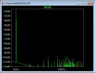
Interestingly the simulations with MOSFETs refuse to behave like predicted in the distortion pattern.
As an example I append two simulations that show the effect. The circuitry with the constant current source working as one half of the push pull stage should generate a lot of second harmonic. In simulation it shows only a tiny little bit.
I will try to find out the reason for the discrepancy, but it will take some time.
It seems to be a good idea to make the push and pull output stages easy reconfigurateable so that you can change by a jumper the way every transistors works:
as a normal source follower or as a constant current source. If I had to build the amplifier today I would go that way. After finishing the amplifier one can explore the sound of the different jumper settings.
In additon the gain of the driver stages should be set to get the same amount of the second harmonic in relation to the third harmonic to keep this relation stable (as far as possible) over output level and power:
In the text in section "d.) controlling k2" a way is described to change the amount of second harmonic. In the appended circuitry that can be done by inserting a resistor (of 60k) between drain and gate of only one (!) of the driver transistors. Thus the current through the resistor that is in parallel to its gate and source will increase and thus the value of the resistor should be reduced (from 1k to 840 Ohm) to get the same gate source voltage as before. As a result you get the same drain quiescent current in both MOSFET driver stages but the stage have different gain.
So I have written it down and completed it to get a whole picture. As a result it deals especially on how to control the distribution and amount of harmonic distortions.
To share the text with you I have written that in English and append it here. I hope you like it.
Interestingly the simulations with MOSFETs refuse to behave like predicted in the distortion pattern.
As an example I append two simulations that show the effect. The circuitry with the constant current source working as one half of the push pull stage should generate a lot of second harmonic. In simulation it shows only a tiny little bit.
I will try to find out the reason for the discrepancy, but it will take some time.
It seems to be a good idea to make the push and pull output stages easy reconfigurateable so that you can change by a jumper the way every transistors works:
as a normal source follower or as a constant current source. If I had to build the amplifier today I would go that way. After finishing the amplifier one can explore the sound of the different jumper settings.
In additon the gain of the driver stages should be set to get the same amount of the second harmonic in relation to the third harmonic to keep this relation stable (as far as possible) over output level and power:
In the text in section "d.) controlling k2" a way is described to change the amount of second harmonic. In the appended circuitry that can be done by inserting a resistor (of 60k) between drain and gate of only one (!) of the driver transistors. Thus the current through the resistor that is in parallel to its gate and source will increase and thus the value of the resistor should be reduced (from 1k to 840 Ohm) to get the same gate source voltage as before. As a result you get the same drain quiescent current in both MOSFET driver stages but the stage have different gain.
Attachments

...
Interestingly the simulations with MOSFETs refuse to behave like predicted in the distortion pattern.
As an example I append two simulations that show the effect. The circuitry with the constant current source working as one half of the push pull stage should generate a lot of second harmonic. In simulation it shows only a tiny little bit.
It seems to be a good idea to make the push and pull output stages easy reconfigurable so that you can change by a jumper the way every transistors works:
...
Interestingly, I have observed the same behavior and have not figured out what is going on. I would expect the anti-phase single-ended stages to sum K2 rather than cancel. It would be nice to understand this behavior before building boards.
...
Interestingly the simulations with MOSFETs refuse to behave like predicted in the distortion pattern.
As an example I append two simulations that show the effect. The circuitry with the constant current source working as one half of the push pull stage should generate a lot of second harmonic. In simulation it shows only a tiny little bit.
...
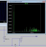
Capacitors (and inductors) can cause problems in the simulation. When I changed the input capacitors to 1000uf (totally unreasonable, but makes the simulation work better), the spectra are much more revealing. The other thing I would change in your simulation is to run it at higher input voltages, like 0.4V. The circuit as presented will not produce more than about 1 watt output before entering Class-AB.
Hello lhquam,
in my last post (with the addition of E1) I changed both input capacitors to 1000µF. The input voltage of 0.1V causes an output swing that is clearly in the class A region. Because this circuitry was intended as a study, the restriction to 1 Watt class A output power is not a problem.
When simulation works as expected, it makes sense to me to change the values to be appropriate for a real amplifier.
One more:
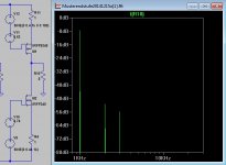
I changed the output transistors of the push and pull stage in circuitry 11 (Q4 and Q5) to MOSFETs IRFP240 and IRFP9240 and tuned the voltages to get the same currents. The distortion spectrum with that is not as expected. It shows a lot of second harmonic. So the MOSFET models do not behave as expected.
I changed the output transistors of the push and pull stage in circuitry 11 (Q4 and Q5) to MOSFETs IRFP240 and IRFP9240 and tuned the voltages to get the same currents. The distortion spectrum with that is not as expected. It shows a lot of second harmonic. So the MOSFET models do not behave as expected.
Attachments
Hello generg,
with your addition of E1 voltage source I get the following.
Did you change anything besides that in your simulation file?
o.k. pr,
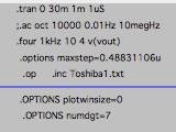
- here you can see your circuit and my changes only the E1 voltage
- my set of Spice directives
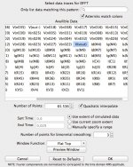
- my distortion results
and now?
🙂
keep in mind I am just a beginner in Spice….
the real Spice master is lhquam…. 🙂
Attachments

Last edited:
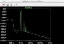
there is a review of the X600.8 with this picture…..the reviewer writes that the distortion is mostly the noise he had in his setting and he calculated the real distortion much lower…
you can find it at Pass Labs homepage new awards….. it is very interesting to read!
you can find it at Pass Labs homepage new awards….. it is very interesting to read!
Attachments
Last edited:
there is a review of the X600.8 with this picture…..the reviewer writes that the distortion is mostly the noise he had in his setting and he calculated the real distortion much lower…
you can find it at Pass Labs homepage new awards….. it is very interesting to read!
Where can I find the review? The THD seems rather high for 5V output, which is only 3.125W if the voltage is RMS. The dBV scale of the graph is consistent with 5V RMS = 13.97dBV.
- Status
- Not open for further replies.
- Home
- Amplifiers
- Pass Labs
- XA.8 single-ended current sources