I plan to show options for adjusting the H2 levels relative to the H3 levels. If we assume we are using IRFP240 and IRFP9240 FETs, and a total of 20 FETs , including those for current sources, then the only parameters to choose from are:
- The number of PP-FETs vs SE-FETs, totaling 20.
- The PP and SE bias currents, totaling around 3 Amps per rail per channel, totaling around 300 Watts idle dissipation, assuming 25V rail.
- The FET source resistance -- 0R47 assumed, but could be different.
For maximum flexibility I would suggest putting the current source in each quadrant of the output stage. This way you are not limited if for whatever reason the final result does not turn out as simm'd. Don't need it don't use it
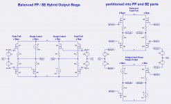
I have been thinking about the XA.8 output stage and have arrived at a way to better understand how it might work. The first figure is a possible (simplified) schematic of the XA30.8 output stage. The send figure is an abstraction of that schematic and its decomposition into balanced push-pull stages in parallel with bridged anti-phase single-ended stages.
With this decomposition it is very easy to understand the H2 and H3 of the each part. Assuming the pp-out+ and pp-out- parts of the balanced push-pull stage are identical, then the equal H2 outputs subtract and are totally nulled and the equal H3 outputs add. The anti-phase H2 and H3 outputs add.
Thus the total output into the load is determined as:
Formulas for these harmonics as a function of the FET KP parameter, the idle currents, and the source resistors (Rs) are forthcoming.
- H1 = 2*H1(PP) + H1(SE+) + H1(SE-)
- H2 = H2(SE+) + H2(SE-)
- H3 = 2*H3(PP) + H3(SE+) + H3(SE-)
BTW: The above generalizes to all even and odd harmonics.
Hello lhquam. The operation of the Bridged Anti Phase SE part is quite interesting, and is highly worthy of a qualitative explanation to go along with its science that you are showing.
it would be simpler to think about unequal left-right SE loading , instead of anti phase SE load
I hope the following adds to understanding the operation of the bridged SE amp.it would be simpler to think about unequal left-right SE loading , instead of anti phase SE load
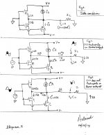
1. Fig. 1 depicts a simplified output stage. Each branch idles at 1 Amp.
2. This bridged amplifier is balanced; meaning Vo=Vo'; because there is no current flowing through the load [I = 0]. The absolute value of Vo or Vo' is taken to be zero volts or at common level.
3. Fig. 2 is a snapshot of the amp during a simultaneous diminished current conduction of the N and P Mosfets. Current flow through each Mosfets is shown at 0.5 Amp each.
4. The remnant of the current output of the CCSs is now progressively diverted in the load as shown whereby the snapshot shows I = 0.5 Amps or Vo>Vo'.
5. Clearly the bridge is unbalanced such that the CCSs appear to operate as current source amplifiers to the load sandwiched between them.
6. In the limit when N and P Mosfets are turn off completely, the new current flowing through the load is 1 Amp
7. Fig. 3 is a snapshot of the amp during a simultaneous increased conduction of the N and P Mosfets. The new current flow through each Mosfet is 1.5 Amp.
8. The CCSs cannot deliver this extra 0.5 Amp to each Mosfet.
9. So, the N and P Mosfets help each other. The bridge is unbalanced such that Vo'>Vo,; because the extra 0.5 Amp flows in the load as shown to the N and P Mosfets.
10. Fig.3 tells that the the CCSs do not contribute any of their current through the load; because they have to satisfy the idle current flow of 1 Amp to each N and P Mosfet.
11. I hope this analysis helped to show how each of the 4 players in bridge deliver current to the load. In Fig 2. the CCSs contribute power to the load. In Fig. 3, the CCSs do not [idle loads], and implies unequal operation during the processing of a sine wave signal; for example.
The next challenge is to superimpose [qualitatively like above] the operation of this bridged SE amp onto its companion the bridged PP amp.
Attachments

The attached image depicts a qualitative description for the operation of a mixed PP/SE amplifier [lhquam's terminology]. The N and P1 Mosfets belong to PP, and P2 Mosfet with its attendant CCS makeup SE.
1. Fig. 1 is a snapshot of the amp at idle. It shows the flow of current and its direction in the Mosfets. An arbitrary 1 Amp idle current is shown. Note that I highlighted the current of CCS as 1*Amp so as to track this origin.
Fig. 2 is a snapshot of the amp as it processes the shaded positive-going component of the input sine wave. Noteworthy is the contribution of current [0.5*A] by CCS through the load Zl.
Fig. 3 is a snapshot of the amp as it processes the shaded negative component of the input sine wave signal. Noteworthy is the absent contribution of current by CCS through the load.
It follows that the mechanism to amplify the input signal is different for the positive-going component of the input signal from that of its negative going in input signal. This is important to grasp/appreciate, and its all due to the SE part. Thereafter, one can extend this descriptive understanding to the bridged system under study.
Other qualitative analyses of operation like this for schematics which I already suggested will sort out their viability; because I know now what is that I am looking for.
Best regards.
Attachments
now just combine that with L-R mirror imaged
Doable. I hope this qualitative explanation for a half side of the bridge did the trick.
Hello buzzforb. The other stuff of H2 and Hn, etc.. is beyond me. Fortunately, it is in the capable, and expert mind of lhquam. I needed a mental picture to understand this mechanism of amplification; derived from my forte of the older days of Organic Chemistry and its never-ending reaction mechanisms which I loved to do [step wise, methodical, no violation of rules] like in this case.Just that easy.
Best regards
I think your explanation was great. I would suggest that to get to the end product, the journey is more involved.
Thanks buzzforb.I think your explanation was great. I would suggest that to get to the end product, the journey is more involved.
I find myself getting more interested in this thread. I hope that I am making a substantive contribution to it. Maybe the following qualitative explanation of graphics fits this bill and pertains to the important SE part of the mixed PP/SE amp which lhquam is addressing.
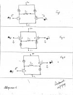
1. An audioDIYer assembles 2 channels of an SE amp by using N-Mosfets. This is depicted [simplified] in Fig. 1. The DIYer then chooses to operate it as either a stereo [L&R channels], or a balanced mono block.
2. A second audioDIYer assembles 2 channels of another SE amp by using P Mosfets instead as depicted in Fig. 2.
3. A third audioDIYer [maybe lhquam] assembles 2 channels of yet another SE amp by using P and N Mosfets instead of dual P or dual N Mosfets as depicted in Fig.3.
4. Note that the L and R branches [channels] of Figs. 1, 2 are mirror images, and thus are expected to give a symmetrical operation in the SE bridged mode.
5. By contrast, the L an R channels of Fig. 3 are not mirror images, and thus are expected to give an asymmetrical mode of operation in their SE bridge amp as I qualitatively explained in an earlier post.This SE bridge amp is expected to have a different harmonic distortion fingerprint than those of Figs. 1, and 2 which maybe and/or are more alike than different.
6. In a later step, one may compound, each of the 3 SE bridged amps with a common dual PP amp to make 3 different compounded PP/ SE bridged amps. The compound of this dual PP amp [maybe F4 per lhquam's post #82] with the SE bridged amp of Fig. 3 is the most interesting for its expected different harmonic distortion fingerprint; which is apparently then manipulated to endow it with special subjective sonics.
Best regards.
Attachments
I think perhaps your polarities are reversed in fig 1 vs fig 2.
You can certainly count on lots of 2nd harmonic in fig 3.
😎
You can certainly count on lots of 2nd harmonic in fig 3.
😎
Yup, that it what my simulations show. Fig 3 is what I called bridged anti-phase single-ended in my post #119. When I tried unbalancing the H2 cancellation using either fig1 or fig2 single-ended, it required 2 FETs worth of single-ended on one side to obtain H2=H3 at 9 Watts.I think perhaps your polarities are reversed in fig 1 vs fig 2.
You can certainly count on lots of 2nd harmonic in fig 3.
😎
Right now I am questioning the Spice models for the IRFP240 and IRFP9240 FETs, thinking that the LTSpice library models are not too appropriate for the currents and voltages used in audio amplifiers. The 9240 lambda of 0.1 causes a serious deviation from square-law and raises the gm of the 9240 way above the 240. I need to measure a bunch of devices at the expected operating currents and voltages to "tune" the Spice models.
I think perhaps your polarities are reversed in fig 1 vs fig 2.
You can certainly count on lots of 2nd harmonic in fig 3.
😎
Thanks Mr. Pass for your correction. Fig 3. is a most fascinating circuit.
Story Part A
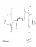
This story revolves around the attached schematic by lhquam from his post #119. Note the following:
1. The balanced push pull [PP] amp [simplified] at the top right corner of image. Most important is that this amp cleanses its output of 2nd harmonic [Pass in post #92], and thus leaves behind a 3rd harmonic fingerprint.
2. The balanced SE amp [simplified] at the bottom right of the image. Most important is that this amp has lots of 2nd harmonic [Pass in post# 136].
3. Make believe next that these two voltage source amps operate independent of each other; but they simultaneously and readily work together; meaning no interference.
4. It follows that the PP and SE balanced amp are readily operated in parallel. lhquam calls this operation a balanced mixed PP/SE. This is shown in the left portion of the image.
Most important is that PP amp pushes through the loudspeaker only a 3rd harmonic fingerprint, and the SE amp pushes through the same load an independent 2nd harmonic fingerprint. An effective accountability and separation of harmonic fingerprints by each amp.
Story Part B deals with the deliberate control over the ratio of 2nd [from SE] to 3rd harmonic [from PP].. Pass in post #88, and lhquam in post #63 emphasized it. This ratio, and its magnitude are very important.
Attachments
Story Part B
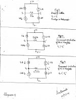
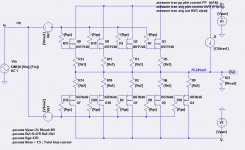
The attached schematic was presented by lhquam in his post #119. It tells this fascinating story:
1. It is one half of lhquam's balanced mixed PP/SE.
2. The P Mosfet of the bottom right side in image and its attendant CCS is the SE amp. The balance of the components make-up the PP amp which maybe diyF4 [lhquam in post #82].
3. As depicted in the schematic, the P Mosfet of SE contributes 20% of the idle current. It follows that it also contributes 20% current through the load during the balanced dynamic operation.
4. This 20% contribution of current by SE carries with it its 2nd harmonic fingerprint [a lot]. By comparison, the 80% contribution of current by PP through the load also carries its 3rd harmonic fingerprint [substantial].
5. It follows that one may see this relative contribution of currents through the load as the generator of a coarse relative ratio of 2nd to 3rd harmonic which needs further fine tuning.
6. Fine tuning of this ratio [ H2/H3] is readily accomplished by decreasing or increasing the emitter resistor of P Mosfet of SE with a simultaneous adjustment in its attendant CCS.
Most important is to determine the solo contribution of 2nd harmonic by balanced SE operating in the load at some arbitrary current which is made equal to the above 20%. Ditto for the contribution of 3rd harmonic by the solo balanced PP at the relative forced 80% current through the load per the above. One thus defines the coarse H2/H3 ratio, and is in the ballpark of defining this optimal ratio. Clearly, a deliberate and highly controllable method to adjust H2/H3.
Story Part C concludes my endeavor.
Attachments
- Status
- Not open for further replies.
- Home
- Amplifiers
- Pass Labs
- XA.8 single-ended current sources