I wonder about f5x trimmed for lowest distortion with SE CS added. Ba1 CS a possibility?
Last edited:
The F5X with the JFET source resistors properly adjusted or with the P3 mod might not be improved much with the variable CS, but it might be worth looking at.I wonder about f5x trimmed for lowest distortion with SE CS added. Ba1 CS a possibility?
I am also looking at a such a modification to an F4, but the approach shown in post #57 looks difficult to accomplish because of the placement of the potentiometer relative to the PFET gate bias circuit.
I think the real value of these mechanisms is for "tuning" the H2/H3 ratio for the "most pleasant" sound.
Of course this is preceded by the 1992 Aleph 0. Later the early version of
the Aleph 1 used a little different technique for modulating the current source,
but I abandoned it for the 2 stage circuit of the later Alephs.
😎
I guess people loaded opamp output stages for class A even before 92 , but never power amps, till Aleph 0. I don`t know is it still patent pending or it is approved? I`m just curious, for instance if the patent is approved to Douglas Self would you have to pay for using this trick in your amps??
Please infuse more clarity in this thread
Hello y'all. I am truly lost in following this thread ; because I am not looking at a "concept" schematic to study, so as to use it to relate to the goals [of Mr. Pass], and then understand the value of the resultant performance of the actual amp. Help!
Hello y'all. I am truly lost in following this thread ; because I am not looking at a "concept" schematic to study, so as to use it to relate to the goals [of Mr. Pass], and then understand the value of the resultant performance of the actual amp. Help!
Well Antoinel, there is a patent by N.P. with a current source in the output. I believe it also has a cascode at the same time??? Don't recall exactly 😀 But maybe that's where most of this comes from???
Well Antoinel, there is a patent by N.P. with a current source in the output. I believe it also has a cascode at the same time??? Don't recall exactly 😀 But maybe that's where most of this comes from???
Thanks flg. I'll take a look in the thread which shows the publications and patents of Mr. Pass for fit.
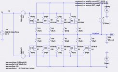
Here is another try at the XA30.8 output stage, based on the images in the 6Moons review.
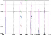
The distortion spectrum is based on a 1kHz, 1 Watt output into an 8 ohm resistive load with the total bias current of 1.5A. The colors correspond to different values of alpha and single-ended bias currents:
The distortion spectrum is based on a 1kHz, 1 Watt output into an 8 ohm resistive load with the total bias current of 1.5A. The colors correspond to different values of alpha and single-ended bias currents:
- Color Alpha SE bias
- Green 0.0 0.0A
- Blue 0.475 0.71A
- Red 0.525 0.79A
- Cyan 0.575 0.86A
- Pink 1.0 1.5A
Attachments
That´s good…!
things get more complicated having a balanced output stage, doing the same alpha on both sides, I suppose.
Much more difficulties to get the k2 bigger….., isn't it?
🙂
things get more complicated having a balanced output stage, doing the same alpha on both sides, I suppose.
Much more difficulties to get the k2 bigger….., isn't it?
🙂
unequal loading will take care of that
however , aiming at final setup through one (voltage) level Spice prediction is wrong
1K hours of ear/brain time is way to go ..........

however , aiming at final setup through one (voltage) level Spice prediction is wrong
1K hours of ear/brain time is way to go ..........
yes!
🙂
….. mostly there is no unequal loading to see in Nelson amps when I count the resistors on the 6moons pictures right, so I suppose at least XA30.5 aims for minimum k2.
If this is true for the XA.8, I do not know, nothing to count…… 🙂
I think the concept changed…..
O.K. Guys this were my last words to this problem…….
I go for ZMs 1k hours listening session and do not care if I am single biased or push-pull….. 🙂
😀😀
It would seem that you would have to set one half with a k2 distortion/phase to your liking while setting other half to a similar but smaller amount with opposite phase. I would assume that when driving the load, these two halves would largely cancel, being of opposite phase, and leave a small remnant of the desired k2 harmonic/phase combo. Talk about time consuming. Probably cheaper to just buy the amp.
If the CS was controlled in certain way,different loading could be handled by a parallel resistor off the main output board. I have always assumed the if you were able to see 10 N channel fets on one channel of his amp, that they were all of the same nature, but if he has a current source on each rail, then it impossible that they are just lined up that way for proper heat dissipation and thermal consistency and just maintained/driven in different ways. Perhaps the XA.8 only has 3 driver fets and 2 CS fets. Automatic higher bias per get by default. I love guessing wrong
well spoken soundshaper….. 🙂 same ideas in my mind.
nothing shapes sound more than guessing wrong!
😀😀😀
nothing shapes sound more than guessing wrong!
😀😀😀
That´s good…!
things get more complicated having a balanced output stage, doing the same alpha on both sides, I suppose.
Much more difficulties to get the k2 bigger….., isn't it?
🙂
I have no idea how Nelson adjusts the current source bias of the XA30.8. I could not detect any hint of a trimpot for such an adjustment in the 6Moon photos of the circuit boards. If Nelson has the goal of a particular H2/H3 ratio, then the output of each half can be measured and adjusted relative to ground to determine resistor values that are soldered in place. That would make it impossible to "tweak" the H2/H3 balance by ear.
The plots shown are based on a 1kHz fundamental. So the dominant peaks at 2kHz are the 2nd harmonics H2, which are the easiest to manipulate with different values for the balance between Vbias1 and CSbias1.
Couple odd ones against case wall. No tellin what's hidden under the main board. Even scarier thought. He did by pre matching fets to certain gain separation. Nah.
Ilquam,
Why do yous think the CS idea would function any differently for f5x?
Ilquam,
Why do yous think the CS idea would function any differently for f5x?
It probably would work for common-source output stages such as in the F5X as well. The idea is to be able to adjust the operating point (bias current) of the fets to compenate for the Kp (transconductance) mismatch between the PFETs and the NFETs. In the F5 with the P3 mod, the overall H2 level can be adjusted for the entire amplification chain. Nelson apparently believes that there is value in controlling H2/H3 in the output stage as well. This might greatly reduce the generation of higher harmonics caused by the global feedback loop.Couple odd ones against case wall. No tellin what's hidden under the main board. Even scarier thought. He did by pre matching fets to certain gain separation. Nah.
Ilquam,
Why do yous think the CS idea would function any differently for f5x?
Reload this Page XA.8 single-ended current sources
Because there is no extra trimpot for SE-current visible on output board it may be assumed that SE-current is set (automatically) together with PP-bias current (on FE-board).
Interestingly that PL has changed numbers of output devices also for older XA.5 amps.
If we compare this with published class A-currents it can be calculated that in each amplifier each output device handles a bias current of about 200mA. May be this value results into a kind of "sweet spot" which Nelson describes in one of his articles.
Wether SE-current is identical to PP-current of one "PP-device" we don't know because values of source resistors are not visible.,,,,,,
I have no idea how Nelson adjusts the current source bias of the XA30.8. I could not detect any hint of a trimpot for such an adjustment in the 6Moon photos of the circuit boards. If Nelson has the goal of a particular H2/H3 ratio, then the output of each half can be measured and adjusted relative to ground to determine resistor values that are soldered in place. That would make it impossible to "tweak" the H2/H3 balance by ear.
The plots shown are based on a 1kHz fundamental. So the dominant peaks at 2kHz are the 2nd harmonics H2, which are the easiest to manipulate with different values for the balance between Vbias1 and CSbias1.
Because there is no extra trimpot for SE-current visible on output board it may be assumed that SE-current is set (automatically) together with PP-bias current (on FE-board).
Interestingly that PL has changed numbers of output devices also for older XA.5 amps.
If we compare this with published class A-currents it can be calculated that in each amplifier each output device handles a bias current of about 200mA. May be this value results into a kind of "sweet spot" which Nelson describes in one of his articles.
Wether SE-current is identical to PP-current of one "PP-device" we don't know because values of source resistors are not visible.,,,,,,
Last edited:
- Status
- Not open for further replies.
- Home
- Amplifiers
- Pass Labs
- XA.8 single-ended current sources