On the other hand 😀
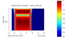
For a filtered ideal dipole impulse response having secondary impulse at 500us and filtered with low-pass filter of 4kHz:

the frequency response looks like this:

And a wavelet can be constructed like this:

Now one can see that there is no dipole notch within the first 500us that is before the secondary impulse arrives.
Even at 1kHz which is well below first dipole notch frequency there is 6dB step at 500us.
- Elias
For a filtered ideal dipole impulse response having secondary impulse at 500us and filtered with low-pass filter of 4kHz:
the frequency response looks like this:
And a wavelet can be constructed like this:
Now one can see that there is no dipole notch within the first 500us that is before the secondary impulse arrives.
Even at 1kHz which is well below first dipole notch frequency there is 6dB step at 500us.
- Elias
Attachments
How does this look any different than any other multiway speaker?
Don't know ...
- basically it looks veeeery good but wavelet analysis usually digs deeper.
But instead of guess working I'm considering to to send you a reg ARTA - so you don't have *that* excuse 😉
Michael
Last edited:
Hello Jean-Michel
Thanks for your plots - but with CMP systems for now I'm always a little bit sceptically with FR plots.
As outlined, the concept of "frequency response" *in general* is flawed when analyzing CMP systems, even more so if measurement and (unavoidable) gating is involved as is the case with John's plot here or any other speaker measurements from any other person - me / anybody included .
At the moment I do not have a good feeling to what extend that must be considered to be severe, though.
Thinking along CMP lines is too new for me too.
Michael
Last edited:
On the other hand 😀
For a filtered ideal dipole impulse response having secondary impulse at 500us and filtered with low-pass filter of 4kHz:
the frequency response looks like this:
And a wavelet can be constructed like this:
Now one can see that there is no dipole notch within the first 500us that is before the secondary impulse arrives.
Even at 1kHz which is well below first dipole notch frequency there is 6dB step at 500us.
- Elias
The point is well taken but moot. It is fine it you like to present such data but it has no relevance to correctly designed dipole speaker. You certainly would not listen to a speaker the rolled off 6dB/octave below 1k hz, would you? And how many times do I have to repeat that the response must be LP filtered below the first dipole peak, preferably at least 1 octave below? I think that it is important to present results which are appropriate to the application. Otherwise it becomes irrelevant, misleading or both.
LP filter the response at about 500 Hz and eq the rersponse below 1K Hz flat. Then look at the result. You can not ignore the effect of the LP filter and equalization, and you can not arbitrarily place the cut off frequency where you like if the intent is a useful. If you want to use a dipole source it must be used correctly.
An externally hosted image should be here but it was not working when we last tested it.
The figure shows the progression as the eq and LP filter are applied and comparison to a true LR4 LP. Any differences between the LR4 and the Eq'ed, LP filters dipole are because of the slight deviation form the target LR4 LP response above 1k Hz where the response.
I don't know how many times I have made this point but apparently some are dead set against showing what really happens with dipole systems when designed correctly.
Don't know ...
- basically it looks veeeery good but wavelet analysis usually digs deeper.
But instead of guess working I'm considering to to send you a reg ARTA - so you don't have *that* excuse 😉
Michael
Actually no. It doesn't. It just looks at the impulse response differently than FR or CSD. As I pointed out months ago, wavelet analyis is noting more than convolution of the impulse with what ever the mother wavelet is.
But instead of guess working I'm considering to to send you a reg ARTA - so you don't have *that* excuse 😉
Michael
I'd rather have someone send me software to do the wavelet analysis.
Most likely reflections from the mic stand for the one around 1ms. I am suspicious of the little glitch in the impulse though. Wonder if that changes with angle.I only have the demo version of ARTA so I can not export the impulse.
... There are small secondary "glitches" in my impulse which arise from reflections/diffraction from other sources. But these are generally more than 30 to 35 dB below the peak of the burst.
Me too.I'd rather have someone send me software to do the wavelet analysis.
Most of the data processing considers the total data as system response. wavelet analysis looks at the response over time. This is valuable for evaluating what is effecting the response by looking at different time window intervals. From the spectrum content of each window segment, it's more convenient to figure out what is causing problems than pure impulse data.Actually no. It doesn't. It just looks at the impulse response differently than FR or CSD. As I pointed out months ago, wavelet analyis is noting more than convolution of the impulse with what ever the mother wavelet is.
CMP?
http://www.diyaudio.com/forums/multi-way/100392-beyond-ariel-146.html#post2297867
http://www.diyaudio.com/forums/everything-else/173283-cmp-framing-what-you-mean.html
🙂
I'd rather have someone send me software to do the wavelet analysis.
Me too.
To the best of my knowledge as for now there is only one free wavelet software available:
Have a look at
http://www.diyaudio.com/forums/soft...wavelet-analysis-available-2.html#post2172102
But be warned - its "under construction" - to say it polite
As for sharing IR files, John – there is good freeware that can do perfectly.
The point is well taken but moot. It is fine it you like to present such data but it has no relevance to correctly designed dipole speaker.
…..
And how many times do I have to repeat that the response must be LP filtered below the first dipole peak, preferably at least 1 octave below?
….
I don't know how many times I have made this point but apparently some are dead set against showing what really happens with dipole systems when designed correctly.
I guess at least some *have* taken your points
😉
– but – as we also discussed some month ago – CMP happens all the way down – or in other words - LP filterning helps to cut the ladder (seen in Elias pix) below the first ladder step, but does by no menas prevent CMP from happening in that range too – CMP is just less obvious below the first dipole peak.
And - you also seem to be "dead set" regarding the point that with CMP systems (OB for example) the whole concept of FR (including all the sophisticated math and measurement methods) is void.
What stays in place is "spectral distribution over time" - the "ladder" shown above by Elias (in extreme case)
Michael
Last edited:
Hello,
Starting from my last "simulation" of the low pass filtered dipole (using a delay rear wave / front wave = 2ms) I equalized the response using a +6dB filter.
You'll see in attached file that the shape of the Impulse Response has been improved by the equalization. Additionally, the CSD from ARTA doesnt' show pathological beahaviour .
There is only one minor thing that I eventually could regret is that the duration of the Impulse of the equalized dipole is something like 10 times the duration of the IR of the (not shown) monopole having the same frequency response (min phase equalized).
Best regards from Paris, France
Jean-Michel Le Cléac'h
Attachments
Last edited:
Hello,
Starting from my last "simulation" of the low pass filtered dipole (using a delay rear wave / front wave = 2ms) I equalized the response using a +6dB filter.
You'll see in attached file that the shape of the Impulse Response has been improved by the equalization. Additionally, the CSD from ARTA doesnt' show pathological beahaviour .
There is only one minor thing that I eventually could regret is that the duration of the Impulse of the equalized dipole is something like 10 times the duration of the IR of the (not shown) monopole having the same frequency response (min phase equalized).
Best regards from Paris, France
Jean-Michel Le Cléac'h
No that is not the case. If the frequency response is identical then so in the impulse. Any differences int he impulse are due to differences between the response of the monopole and the eq'ed dipole.
Hello,
I don't think so,
min phase equalizing with a -6dB slope is the difference here. (-6dB equalizing being equivalent to an additional low pass filter having a cut-off lower than 10Hz e.g. ).
I can show for the same treatment (except -6dB equalization) the simulations for the monopole case and the dipole case... (but as you seem to deny what I say I would prefer someone else does the simulation...)
Best regards from Paris, France
Jean-Michel Le Cléac'h
No that is not the case. If the frequency response is identical then so in the impulse. Any differences int he impulse are due to differences between the response of the monopole and the eq'ed dipole.
http://www.diyaudio.com/forums/multi-way/100392-beyond-ariel-146.html#post2297867
http://www.diyaudio.com/forums/everything-else/173283-cmp-framing-what-you-mean.html
🙂
And - you also seem to be "dead set" regarding the point that with CMP systems (OB for example) the whole concept of FR (including all the sophisticated math and measurement methods) is void.
Michael
You just seem to want to ignore the physics. What I am dead set against is ignoring reality. Please explain how two systems with identical impulses can behave in any manor but identical. The entire wavelet analysis is just convolution with the system impulse, regardless of how the impulse is generated. If I gave you the impulses for a 2-way dipole and a 2-way box speaker designed to have the same frequency response what do you thing the wavelet analysis would show that was different?
What I see here is a bunch of ifs. All the arguments put fourth are based on "if something behaves like this, then this happens". The problem is, as I have shown, things don't behave like that. So then you go off in some other direction, postulating a new behavior which also isn't applicable.
I mean, forget FR, when I stick my mic out there and measure the response of a dipole system it either has a double impulse or it does not. It is not open to argument.
What is this the impulse of, a dipole system or a monopole? What will any post processing tell you in that regard.
An externally hosted image should be here but it was not working when we last tested it.
The point is that setting up some idealized test case to demonstrate what you want is far from applying the process to an example of unknown source and trying to interpret the result.
If you do not understand what is going on with the impulse how can you interpret what the wavelet analysis tells you? And once again, FR, CSD, Burst response, wavelet, step response...., are all just post processing of the impulse. If you don't understand what caused a glitch in the impulse the wavelet analysis will only show you the glitch in a new way. It will not tell you the origin.
Most likely reflections from the mic stand for the one around 1ms. I am suspicious of the little glitch in the impulse though. Wonder if that changes with angle.
If you are referring to the glitch that appears just after the negative swing begins to recover, it is associated with the tweeter. It also happens to be on the order of a sample length.
Hello,
You'll find in attached file a 48kHz 16bits wave file (in txt format) with 2 pulse responses of simulated monopole and dipole.
Both IR responses receive the same treatment (except -6dB /octave equalization of the dipole).
( 20Hz HP 2nd order Butterworth + 200Hz LP 3rd order Butterworth were applied to simulate the filtered loudspeaker)
You'll see that the duration of the dipole is 4518 samples when the duration of the monopole is 2200 so the ratio is a liitle more than 2 (a first estimation without HP filter leads me to a ratio = 10).
( is it related to the long tail of the IR of the NaO ?...)
Best regards from Paris, France
Jean-Michel Le Cléac'h
Attachments
Hey John, don't be so serious ! 😉 I mean, we both listen to OB and enjoy its presentation, no ?
- see – to me it seems there are two veeery different levels we are discussing at.
I do not have any problem with you asking „Anyway, where is the CMP distortion?“ *if* we stay on a low level of „it does not matter *for me*“.
Even when you tell us „CMP does not matter *usually*“ *and* bring some prove for that too, would not be a problem for me.
Actually I'd even appreciate that.
But in both cases you will *have to* accept CMP to be a real issue in audio. How much it counts is the never ending story – ( its up to your taste to make your pick....)
What you will have to prove first though is to what extend the flawed „FR concept“ still is valid.
That FR concept *is* void with CMP systems - again – you will *have to* accept first.
So – I'd suggest we claryfy first if you want to discuss „Anyway, where is the CMP distortion?“ at the level of practical speaker building (in the sense of "my taste is all that counts") – or – if you want to argue about CMP concept's validity *in general*.
In the latter case I'd find exchange of IR files helpful...
🙂
Michael
Last edited:
You have got to be kidding. You create a construct you call CMP that somehow is not subject to the well known relationships between an impulse response and all of the other representations that can be derived from it, then state that someone else must "re-prove" the current understanding or essentially disprove your claims of a supposedly "flawed FR concept" based on your conjecture???But in both cases you will *have to* accept CMP to be a real issue in audio. How much it counts is the never ending story – ( its up to your taste to make your pick....)
What you will have to prove first though is to what extend the flawed „FR concept“ still is valid.
At one point I thought that something of benefit might result from this thread and indeed it has for me, but it has nothing to do with this nonsense called CMP. I certainly understand dipoles better, especially how it is manifested in an impulse response with John's input, but this concept called CMP is utter nonsense. It is incumbent on you, the proponent, to prove your case. Nothing of the sort has been presented.
Dave
You have got to be kidding.
take your pick:
http://www.diyaudio.com/forums/everything-else/173283-cmp-framing-what-you-mean.html#post2313209
😉
Michael
- Status
- Not open for further replies.
- Home
- Loudspeakers
- Multi-Way
- WTF!? Wavelet TransForm for audio measurements - What-is? and How-to?