Hello,
You'll find in attached file a 48kHz 16bits wave file (in txt format) with 2 pulse responses of simulated monopole and dipole.
Both IR responses receive the same treatment (except -6dB /octave equalization of the dipole).
( 20Hz HP 2nd order Butterworth + 200Hz LP 3rd order Butterworth were applied to simulate the filtered loudspeaker)
You'll see that the duration of the dipole is 4518 samples when the duration of the monopole is 2200 so the ratio is a liitle more than 2 (a first estimation without HP filter leads me to a ratio = 10).
( is it related to the long tail of the IR of the NaO ?...)
Best regards from Paris, France
Jean-Michel Le Cléac'h
Jean-Michel,
A couple of things that must be considered. First, if both have the same treatment except for the 6dB/octave Eq, then the resulting amplitude responses are not identical and I would expect some small differences in the impulse. The differences arise because 1) unless the eq extends to DC the dipole will undergo a transition from a 2nd order roll off to a 3rd order roll off below where the eq stops. 2) Since you are applying only the 6dB/octave eq, the response, at some point above the upper limit of the eq, while it may be attenuated, will still have the comb filtering and therefore, again will not match the filtered monopole response. Identical amplitude and minimum phase will yield identical impulse. If the impulse is not identical then the amplitude/phase response is not identical.
Of course, all this is also really pretty moot too because in any real speaker, monopole or otherwise, the acoustic amplitude will never be in exact match to the specified target so the actual impulse will always be somewhat different than that of the target. A longer tail for an impulse indicates some difference in the low frequency cut off.
If you want to try this. With you monopole, use you 20 Hz B2 HP, 200 Hz, B3 LP and then compare it to a 5Hz B1 HP cascaded with a 20 Hz B2 HP then a 200 Hz B3 LP. Same basic response but there is a transition form 2nd order roll off to 3rd order roll off and the result is a longer tail for the impulse as well as some other differences, all related to the difference in the low frequency cut off.
As for the impulse of the NaO what ever it is, it is not a result of it being dipole or monopole or otherwise. It is a matter of what the response is.
Again, stick a mic out, measure the impulse, FFT it and obtain the frequency response. That process has no idea of how the impulse was generated, dipole, monopole, quadrapole, hexapole, what ever. If the impulse is the same the frequency response is the same, the CSD is the same, the burst response is the same, the wavelet analysis is the same...... If the impulse is difference, yada, yada, yada.
We can concocted all type of arguments that show systems with different impulses behave differently. That is expected. And it seems that some of the posts here are directed at implying that an OB system can not have the same impulse as a direct radiator. If the impulse is different then everything is different. If it is the same, everything is the same. So concocted examples, intended to be different do just that. But I guess stepping out in the the real world and measuring an impulse is threatening.
This is not a knock on wavelet analysis. If some find it useful then that is good. But it is a knock on the ideal that OB system suffer form CMP distortion. They do not, if correctly designed. There is no double impulse. The comb filtering effect shown in what ever analysis is applied to the impulse is a result of a double impulse. So where is the argument to support the effect when measurements don't show a double impulse?
Michael,
Frequency response? Forget about it. It is just a representation of the impulse. Wavelet analysis is not more valid, it is just a representation of the impulse. We can stick a mic out and measure a system's impulse. We can input any time dependent signal and measure and record what we get out. The bottom line is that the output is the input convolved with the system impulse. So it comes back to what I said. Look at the impulse I posted. Is it a dipole or a monopole? Does it matter? There is nothing there to tell you what it is. But the FFT of that impulse will tell you what the frequency response of that system, and any system with similar impulse, will be (whether you think it meaningful or not); and a wavelet analysis of that impulse will tell you what the wavelet analysis of that system, or any system with similar impulse, will be. Now, cross correlate; any system with the same frequency response will have the same wavelet analysis because both are derived from the same impulse impulse.
. But it is a knock on the ideal that OB system suffer form CMP distortion. They do not, if correctly designed.
…
So where is the argument to support the effect when measurements don't show a double impulse?
You may remember what I've shown month ago and also is layed out in my CMP paper, John.
Measurements published there *do* show the kink form CMP behaviour below dipole peak. This kink is not expressing in a clear „double pulse“ (doublet) but it *is* how CMP „distortion“ looks like at in this range.
The CMP ladder shown by Elias tells the same story - even if you hide anything above the first ladder step - it still is a ladder you have to deal with (well, the rest of) 😉
So – again :
- you simply cant avoid CMP here
- there simply is no way to „correctly design“ OB with respect to CMP
- there may be trade off differences though with respect to CMP (as with nude OB for example)
Michael,
Frequency response? Forget about it.
At „frequency response“ I now look as being a mere *concept*.
A simple concept - just as the concept of CMP is one .
If we define FR as to be spectral distribution at steady state – I see it being time independent only for an ideal FR – meaning, a ruler flat FR from DC to infinity would be the *only* FR that would translate into a time independent spectral distribution. (ideal CSD decay for example)
Any real world FR (without CMP entering the picture of course) will have time dependent spectral distribution - but – this time dependency is a well defined one – and – its definitely *without abrupt changes* in the time line.
There is no way to define a FR with CMP involved.
As said – there are simply more then „one FR“ involved with CMP systems...
Or - looking at it the other way around - FR concept relays on the premise that time dependency is not discontinuous (as is with CMP systems).
So – as a simple consequence - the whole concept of „FR“ is void when it comes to CMP systems (strictly speaking).
This IMO is not the case for „impulse response“ concept.
Exciting any speaker with a Dirac stimulus and engrave its amplitude in wax – still valid !
Not so for the math to translate this IR into frequency domain – or possibly better said – such a translation is what it is – the output of something that simply cant be expressed in „FR“ terms.
But as said elsewhere - in *this* thread I think such a discussion is pretty OT
Michael
Last edited:
Michael, the Frequency Response of a system is the FT of its entire impulse response. You constantly confuse Frequency Response with spectral content. The spectral content of sections of a signal (whether the signal is an impulse response or not) can vary, the Frequency Response of a system (more particularly an LTI system) does not vary, just as its impulse response does not vary.
Michael, the Frequency Response of a system is the FT of its entire impulse response. You constantly confuse Frequency Response with spectral content....
A FR is the spectral distribution at steady state - or after infinite time.
Am I right so far ?
Spectral distribution at all time slots form zero to infinity are well defined by FR.
Am I right so far ?
How then will anybody ever be able to pack a CMP ladder into FR (figuratively speaking) ???
Or - looking form the other side - how, in your opinion - would a FR look like that also reflects CMP behaviour (take the above most simple "ladder-system" for example please) ???
Michael
Last edited:
No. FR has nothing to do with steady state (deja vu here). The system's Frequency Response is the FT of its impulse response. That is the definition of the FR. If the impulse response is short, it is the FT of that short IR. If the IR is long, it is the FT of that long IR. However long the IR is, that is what gets FT'd to produce the FR.A FR is the spectral distribution at steady state - or after infinite time.
Am I right so far ?
Again, no. Read the above. Try and stop equating system FR with spectral content, the only time FR is the same as spectral content is when you take the FT of the entire response of the system to an impulse. If you want to see how the output of the system evolves over time for any given input, convolve that input with the IR. The convolution can be done in the frequency domain if desired, in which case you need to FT the entire input signal, however long that is, multiply it by the FT of the IR (which is the FR), then invFT the result, which gives you the time signal which is the system output.Spectral distribution at all time slots form zero to infinity are well defined by FR.
Am I right so far ?
"Measurements published there *do* show the kink form CMP behaviour below dipole peak. This kink is not expressing in a clear „double pulse“ (doublet) but it *is* how CMP „distortion“ looks like at in this range."
You have to lowpass the test signal to the correct frequency.
There is no such thing as an abruptly starting sine wave of a single frequency.
Or to say it in another way. A sine wave of a single frequency can only be expressed as steady state.
Or did I miss something?
I have also been thinking about this type of time domain "distortion" or what to call it. And how it will relate to short "bursts" of sound.
Like an explosion or the like.
From the impulse response if a TH (lowpassed) and the same overall response but simulated I got very close IR resemblance. Only a slightly different but small kink at the end.
The hornresp sim shows the same kink btw.
At least with a TH you are restricted to the same behavior in all directions.
Can't be that good with a TL or similar with large driver to terminus distance.
So, for simplicity, let us take Elias example of a CMP system:
A system the has a echo (impulse) at 2ms shown below :
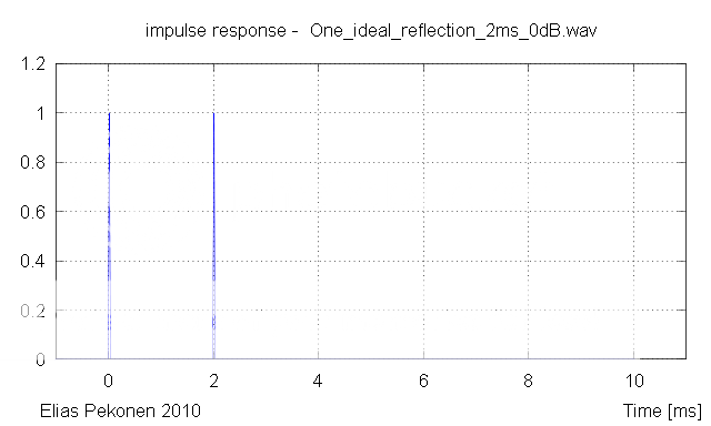
Wich translates into a time freqeuncy plot like below - when this system is stimulated by an equally distributed spectra for exactly 4ms :
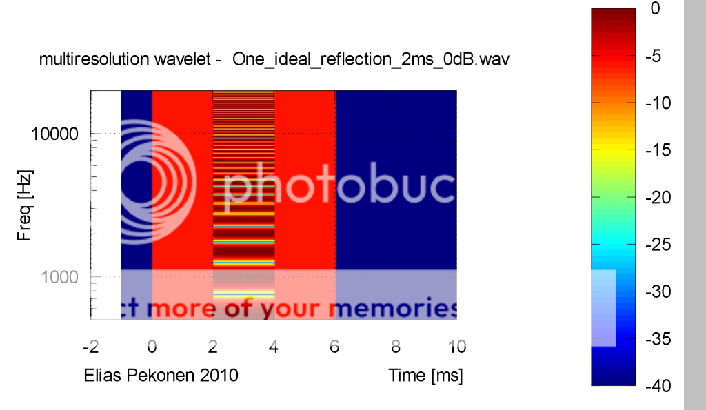
As can be seen - the IR-peak is ideal - besides it comes along as an echo after 2ms again.
Following your lines - this means, that if a FR is calculated form the IR of 2ms duration it would capture all and everything and be a perfect translation into frequency domain - at least in your terms whereas calculation from a windowed IR would not capture the behaviour of that system.
First case:
capture first peak only:
Its pretty easy to imagine that if we would do a FR translation from the first pulse only (windowning 0 to 1ms for example) the frequency response would be ruler flat.
This *should* translate - as said a posting ago - into a time frequency plot being simply deep red as long as - *exactly* as long as (!) - stimulated by an equally distributed spectra .
Now obviously this is no good representation of the CMP (ladder) behaviour
😀
--------------------
Following your lines - you suggest to calculated FR form entire IR (2ms duration here) to capture each and everything and to get a perfect translation into frequency domain - at least in your terms
Second case:
capture first *and* second peak:
This is your turn, John!
And also tell us which FR now is the valid one, please...
😉
Michael
A system the has a echo (impulse) at 2ms shown below :
Wich translates into a time freqeuncy plot like below - when this system is stimulated by an equally distributed spectra for exactly 4ms :
As can be seen - the IR-peak is ideal - besides it comes along as an echo after 2ms again.
Following your lines - this means, that if a FR is calculated form the IR of 2ms duration it would capture all and everything and be a perfect translation into frequency domain - at least in your terms whereas calculation from a windowed IR would not capture the behaviour of that system.
First case:
capture first peak only:
Its pretty easy to imagine that if we would do a FR translation from the first pulse only (windowning 0 to 1ms for example) the frequency response would be ruler flat.
This *should* translate - as said a posting ago - into a time frequency plot being simply deep red as long as - *exactly* as long as (!) - stimulated by an equally distributed spectra .
Now obviously this is no good representation of the CMP (ladder) behaviour
😀
--------------------
Following your lines - you suggest to calculated FR form entire IR (2ms duration here) to capture each and everything and to get a perfect translation into frequency domain - at least in your terms
Second case:
capture first *and* second peak:
This is your turn, John!
And also tell us which FR now is the valid one, please...
..., the only time FR is the same as spectral content is when you take the FT of the entire response of the system to an impulse.
😉
Michael
Last edited:
You have to lowpass the test signal to the correct frequency.
There is no such thing as an abruptly starting sine wave of a single frequency.
Or to say it in another way. A sine wave of a single frequency can only be expressed as steady state.
Or did I miss something?
.
Yeah I think you missed something.
Low pass filtering does *nothing* to change CMP behaviour - as said - you *can* cover CMP-"ladder" above the first ladder step by low pass filtering - but you still have to deal with a CMP-"ladder" at the frequency range below.
The low pass filtering of OB is to keep directivity controlled but has nothing to do with CMP issue (well at first hand).
As for the sine bursts - look at my measurements - the kink is there - and its exactly like predicted, easy to repeat for everybody in case of.
Michael
Last edited:
"Low pass filtering does *nothing* to change CMP behaviour"
Didn't say it would.
You are however involving frequencies higher than the sine wave you state (25Hz at the lowest).
And the same higher frequencies are the main reason for the "kink" in the wave shape.
Use a cosine envelope or something. It has a more limited spectral distribution around the central frequency.
System Test
One can't deny the significance of CMP above the "peak"
However I'm not so sure it is as big problem below as you show in the paper.
After all you have to poke a hole in the "1/4 wavelength summing perfectly" rule first.
To help explain what I mean.
Here is a 100Hz 10 cycle burst
http://img202.imageshack.us/img202/1610/sine.png
Here is a 100Hz 10 cycle burst with a cosine envelope (or close)
http://img707.imageshack.us/img707/5021/cosine.png
A quickly done in Audacity so it might not be 100% correct. It does show the trend however.
My point is that the straight burst have enough high frequency content due to starting (and stopping) abruptly to make the "kink" at 25Hz questionable in validity.
I have no problem in being wrong but I hope you understand what I mean first.
Yeah I think you missed something.
Low pass filtering does *nothing* to change CMP behaviour - as said - you *can* cover CMP-"ladder" above the first ladder step by low pass filtering - but you still have to deal with a CMP-"ladder" at the frequency range below.
The low pass filtering of OB is to keep directivity controlled but has nothing to do with CMP issue (well at first hand).
As for the sine bursts - look at my measurements - the kink is there - and its exactly like predicted, easy to repeat for everybody in case of.
Michael
Micheal,
You continure to make the same mistake over and over because you simple don't follow through on what is being explained to you and you have rejected the underlying truth that minimum phase equalization applied to a minimum phase system corrects the response is the time domain as well as in the frequency domain.
If you take any of your CMP systems, as you call them, and in particular an OB result, and FFT the multi-impulse you will get a minimum phase transfer function (which everyone else on earth recognizes as the frequency response of the system). If you then apply minimum phase equalization to that system to make the transfer function identical to the minimum phase target transfer function of your choice, and then take the IFFt of that equalized result, the impulse response will be identical to the impulse of the target transfer function and the equalized system will have the same, identical, time response as the target.
Anything you show that is different is because you haven't performed something correctly.
Again, it is the case of concocted examples that show something not related to the system being discussed.
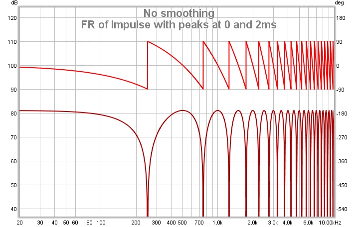
Michael, here is the FR of that system (phase above, magnitude below).A system the has a echo (impulse) at 2ms shown below :

That is the system's only FR. If you take an inverse FFT of that FR, you will get back the original impulse response. If you multiply that FR by the FR of any input you care to apply to the system and take the inverse FFT of that product, you will get the output the system will produce in response to that input. That is the meaning of the FR of a system. It is the frequency domain description of how the system behaves, just as the impulse response is the time domain description.
The wavelet analysis shows the varying spectral content of narrow slices of the impulse response over time. It is a useful plot, but it does not show the system's frequency response, that is not its purpose.
"Low pass filtering does *nothing* to change CMP behaviour"
Didn't say it would.
You are however involving frequencies higher than the sine wave you state (25Hz at the lowest).
And the same higher frequencies are the main reason for the "kink" in the wave shape.
.
Sure, the measured system (NEO3 in OB) isnt exactly a „single tone“ system
When I said „Low pass filtering does *nothing* to change CMP behaviour“ this was meant at the level of „basically nothing“ meaning – CMP is involved anyway.
That the „kink“ gets „smoothed“ out with LP filtering – due to diminished high frequency content - I've shown already in the simus beforehand
Michael
Anything you show that is different is because you haven't performed something correctly.
Again, it is the case of concocted examples that show something not related to the system being discussed.
Our CMP discussion – as far as I remember - has ended some time age at the state :
„Nothing wrong with you measurement,....
It is not the measurements which are flawed, but your logic.“
http://www.diyaudio.com/forums/multi-way/100392-beyond-ariel-142.html#post2266852
---------
In my opinion 🙂 I have measured an OB speaker – so the examples I've shown seem to apply.
As for the rest – I do not question that you can transform / translate from IR to FR and vice versa „in general“ but I question that *with CMP involved* FR is a valid representation of the system.
There is a nice analogy:
Take the plot linked here:
http://www.diyaudio.com/forums/multi-way/100392-beyond-ariel-147.html#post2313024
and lets say that the translation *with CMP systems* from IR to FR is the same as translating from color into luminescence.
We easily see that we lost something, once we have done translation form IR into FR
Michael
Michael, here is the FR of that system (phase above, magnitude below).
That is the system's only FR. If you take an inverse FFT of that FR, you will get back the original impulse response.
Good
And - at what time slot does that spectral distribution actually happen ?
And – from that FR – is spectral distribution for all time slots from zero to infinity determined (the way as it is the case with non-CMP systems) ?
Michael
Michael, at some point I hope you will comprehend how nonsensical that question is. As I keep telling you, the system FR is not a spectral distribution, it is not something that occurs at some particular time. The FR is a frequency domain system description, it is the FT of the system's impulse response. It is a way of describing how the system behaves, just as "misunderstands all attempts to explain what should by now be obvious" is a way of describing your behaviour. The description of the behaviour is not a picture of the output, it tells you how to determine the output given the input.at what time slot does that spectral distribution actually happen ?
Yes, given the FR you can determine the output of the system at any time for any input. The FR is a complete system description.And – from that FR – is spectral distribution for all time slots from zero to infinity determined (the way as it is the case with non-CMP systems) ?
Hello,
Elias as treated the case of the pulse reflection. I'll concentrate on the dipole case which is different, the inverse impulse coming from the rear of the loudspeaker interfering with some delay with the impulse coming from the front of the loudspeaker.
John advocacy is that the composite pulse thus obtained is "min phase" and such it can be equalized by a simple 6db/octave filter (or a more complex...). The idea being that correction of the frequency response curve will also produce a correction on the phase curve. From this should results an improvment in the Impulse Response (IR).
The weak point is the hypothesis than the composite impulse mentionned above is "min-phase".
We knows that for a frequency below the dipole peak (first peak on the frequency response) the level decreases aproximatively with a slope of 6dB/octave. But does a corresponding phase variation exists as in the min-phase hypothesis ?
The answer is NO.
I am not the best mathematician so I'l prefer to demonstrate this on a pulse corresponding to a theorical dipole having a null at 500Hz. This means that using a sampling frequency of 48kHz the inverse "rear" pulse is delayed of 96 samples from the front pulse. Also I assume that the rear pulse and the front pulse have the same intensity). Also only the frequency lower than 500Hz are considered.
On the graph screen_1_.gif (see attached file) we can see that the composite impulse response is perfectly symetrical around the point where the main positive arch encounters the main negative arch. What does this means: according to the Fourier method that signal can be decomposed in a series of sine (without any cosine components). This means also that the phase of all the components is constant (90°). There is no phase variation (other than the linear variation that could be due to the choice of another origin of time). This explains also why the group delay curve obtained by the analysis of that composite signal is constant.
Then you can see the result of the -6dB/octave min phase equalization performed on the very same composite impusle response (attached graph screen_2.gif).
In conclusion the 6dB slope below the first peak of a dipole due to the interfering between a delayed inverted "rear" pulse and a "front" pulse cannot be min-phase equalized. A linear phase equalization has to been used.
Best regards from Paris, France
Jean-Michel Le Cléac'h
Attachments
Our CMP discussion – as far as I remember - has ended some time age at the state :
„Nothing wrong with you measurement,....
It is not the measurements which are flawed, but your logic.“
http://www.diyaudio.com/forums/multi-way/100392-beyond-ariel-142.html#post2266852
---------
In my opinion 🙂 I have measured an OB speaker – so the examples I've shown seem to apply.
As for the rest – I do not question that you can transform / translate from IR to FR and vice versa „in general“ but I question that *with CMP involved* FR is a valid representation of the system.
There is a nice analogy:
Take the plot linked here:
http://www.diyaudio.com/forums/multi-way/100392-beyond-ariel-147.html#post2313024
and lets say that the translation *with CMP systems* from IR to FR is the same as translating from color into luminescence.
We easily see that we lost something, once we have done translation form IR into FR
Michael
As I said Micheal, you have presented a result which substantiates you position. But that case is not representative of a correctly designed OB system. I won't go into the rest as JohnPM has answered those questions. But IR>FR>IR looses nothing.
However, perhaps some discussion of how OB midranges and tweeters should be designed will help.
First let's understand one thing. With any driver mounted on an OB there are two thing that we need to recognize. First, the response from the rear side that wraps around the baffle is alway lower in amplitude than the direct response from the front simply due to the increased path length. Second, the response that wraps around the baffle is always (at best) a low pass filtered version of the front response due to directionality of the source.
With that in mind I will start by looking at a midrange driver. The figure below shows at the top what the unequalized response of such a driver might look like. In this case I have only considered the small difference in amplitude between front and rear response. There is comb filtering above the first peak but the dips are finite since the rear amplitude is lower than the front. If the low pass filter effect were included in the rear response, the depth of the dips would decrease as frequency increased. At low frequency the response flattens out, again due to the slight differences in amplitude.
Since the dips are of finite depth and since the response in minimum phase, minimum phase EQ could be applied to flatten the response. The green traces show what that EQ might look like. On the left complex EQ is applied which would flatten the response over the full range. On the right a simpler EQ is applied, flattening the response only below the first dipole peak.
The blue traces then show the EQ'ed driver response. With the simple EQ the useful range is indicated. In reality this same useful range applied to both forms of EQ when off axis behavior is considered.
The lower traces show the result of applying a text book LR4 LP filter to the Eq'ed responses. The complex EQ yields an exact LR4 LP response. The simple EQ deviates a little and has a slightly steeper roll off although if the response were visible to higher frequency we would see evidence of the comb filtering though highly attenuated.
Lastly, the impulse response of the two cases is shown. They are pretty much identical except that the case with the simple EQ is shiffted a little to the right. This is a result of the net steeper roll off which results in slightly more group delay. Neither response shows evidence of any double impulse behavior. In reality there would be some very weak double impulse behavior for the simple EQ case at high frequency, but due to the high level of attenuation (better the 60dB) it is unlikely that it would have any audible effect.
An externally hosted image should be here but it was not working when we last tested it.
So any so called CMP behavior just isn't present in this correctly designed OB application.
Next let's consider a tweeter. This is where I think you make mistakes. When you place a Neo 3 on a baffle, or even free standing, the dipole peak is going to be around 2k or 3k Hz with the first dip between 4k and 6k Hz. So the rule about using the dipole response only below the peak is out the window. Something else has to be done. This is where wave guides come in as I used in the Note. Below is a figure showing what is going on:
An externally hosted image should be here but it was not working when we last tested it.
On the left side is the behavior without a wave guide. Ont he right, a wave guide is used to prevent the rear response from wrapping around to the front side at higher frequencies. The wave guide basically LP filters the rear response as it wraps around the baffle thus any so called CMP behavior is limited to low frequency in this case. Here we don't even have to worry about EQ'ing the low frequency response because we are just going to attenuate it with a high pass filter anyway. The lower plots show the comparisons for the now WG and WG cases and compare the resulting responses to the ideal LR4 HP filter response. Both cases show CMP behavior in the impulse response of the unfiltered driver, but to different extents (red traces). The filtered case w/o WG shows some CMP behavior remains (green trace) when compared to the true LR4 HP response shown in Blue. The case with wave guide shows no observable CMP behavior. The test impulse is a unit pulse of 0.1 msec width.
So, your Neo tests are just fine, but they are not what should be done when correctly designing a dipole or OB system. A correctly designed dipole or OB system takes care to assure that and so called CMP or double impulse behavior is eliminated.
Hello,
Elias as treated the case of the pulse reflection. I'll concentrate on the dipole case which is different, the inverse impulse coming from the rear of the loudspeaker interfering with some delay with the impulse coming from the front of the loudspeaker.
John advocacy is that the composite pulse thus obtained is "min phase" and such it can be equalized by a simple 6db/octave filter (or a more complex...). The idea being that correction of the frequency response curve will also produce a correction on the phase curve. From this should results an improvment in the Impulse Response (IR).
The weak point is the hypothesis than the composite impulse mentionned above is "min-phase".
We knows that for a frequency below the dipole peak (first peak on the frequency response) the level decreases aproximatively with a slope of 6dB/octave. But does a corresponding phase variation exists as in the min-phase hypothesis ?
The answer is NO.
I am not the best mathematician so I'l prefer to demonstrate this on a pulse corresponding to a theorical dipole having a null at 500Hz. This means that using a sampling frequency of 48kHz the inverse "rear" pulse is delayed of 96 samples from the front pulse. Also I assume that the rear pulse and the front pulse have the same intensity). Also only the frequency lower than 500Hz are considered.
On the graph screen_1_.gif (see attached file) we can see that the composite impulse response is perfectly symetrical around the point where the main positive arch encounters the main negative arch. What does this means: according to the Fourier method that signal can be decomposed in a series of sine (without any cosine components). This means also that the phase of all the components is constant (90°). There is no phase variation (other than the linear variation that could be due to the choice of another origin of time). This explains also why the group delay curve obtained by the analysis of that composite signal is constant.
Then you can see the result of the -6dB/octave min phase equalization performed on the very same composite impusle response (attached graph screen_2.gif).
In conclusion the 6dB slope below the first peak of a dipole due to the interfering between a delayed inverted "rear" pulse and a "front" pulse cannot be min-phase equalized. A linear phase equalization has to been used.
Best regards from Paris, France
Jean-Michel Le Cléac'h
Jean-Michel,
This is incorrect. The dipole roll off is minimum phase. And it can be eqed in theory. In your example you have not applied eq to DC. When this is done, the GD will be zero and constant. When the eq stops at some point then there is a pole at that frequency. Thus, the amplitude, phase and GD at low frequency will be similar to that of a 1st order high pass response with pole at the frequency at which the eq is stopped. It is all MP.
Now in practice we can not eq anything to DC. Thus if you want to make the GD zero at low frequency then some form of phase linearizion must be applied. But this has noting to do with whether or not the response is MP and whether or not MP eq will correct the problems of amplitude and phase. The figure below shows what happens when the eq is applied to DC and when it is stopped at 4 Hz. There is a pole at 4 Hz. It is that pole that introduce the turn up in GD. Idenitical to a 4Hz, 1st order HP filter.
An externally hosted image should be here but it was not working when we last tested it.
Ultimately this low frequency contribution to the GD is a separate issue because, say for a woofer system, the woofer will probably roll off 2nd order at 20 to 25 Hz anyway and the GD associated with that roll off would be far more than that arising from the curtailing of the dipole eq. These are different issues. 1) dipole eq and MP behavior, 2) low frequency GD correction due to finite system cut off frequency.
Hello John,
I tried to equalize above 1 Hz (previously it was 10Hz) and the result is better now.
Above which frequency the NaO is "dipole" equalized?
As you said, the loudspeaker itself will bring its own contribution to level and phase variation at low frequency and this is probably the main origin of the tail we observe on the measured IR of the dipole (rise in group delay at low frequency).
The choice of the frequency above which the equalization is performed has to be also done in order for the coil to not get out of the gap to easily (Xmax...).
In the document
http://infraplanar.free.fr/Mesures-champ-libre.pdf
you'll see in fig 21 the free field measurement at 5 meters of a large dipole commercialzed under the label "Infraplanar".
We can see the 6dB slope very easily (the whole curve until 500Hz is consistent with a diffrence of path of 96centimeters between the rear wave and the front wave).
We had hard discussions about the need or not to equalize it.
When listening in proximity (from 1 to 3 meters)
at 1 meter, the intensity from the front wave begins to dominate and the response get flatter. This can be seen in figures 008 and 020 (taken at 1 meter at 45° and 0° respectively). At the moment I don't know a single listener of that Infraplanar who would use equalization. May be if they read you they'll change your mind...
Best regards from Paris, France
Jean-Michel Le Cléac'h
Jean-Michel,
The dipole roll off is minimum phase. And it can be eqed in theory. In your example you have not applied eq to DC. When this is done, the GD will be zero and constant. When the eq stops at some point then there is a pole at that frequency. Thus, the amplitude, phase and GD at low frequency will be similar to that of a 1st order high pass response with pole at the frequency at which the eq is stopped. It is all MP.
Now in practice we can not eq anything to DC.
- Status
- Not open for further replies.
- Home
- Loudspeakers
- Multi-Way
- WTF!? Wavelet TransForm for audio measurements - What-is? and How-to?