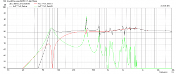
sure, here is the original sim from mathcad and the one I've done in the new software. Not 100% identical but pretty much the same.
One of the nice features of the Leonard audio software is the ability to save driver files and enclosure designs allowing easy sharing of designs for others to play with.
One of the nice features of the Leonard audio software is the ability to save driver files and enclosure designs allowing easy sharing of designs for others to play with.
Attachments
There's always going to be some variation, especially when it comes to damping & the differences between types &c.
One point I should mention that you don't necessarily pick up from the graphs etc. is that the alignments I use are usually related to the driver's inherent response (as separate from the T/S curve) which is one of the many reasons I don't like shoe-horning drivers into boxes designed for something else. In this case, it's quite forgiving, fortunately, and the unwanted harmonic modes in practice will be rather less due to the folds.
I like Pete's software -very impressive so far. Shame Martin felt he had to call it a day, but what with the changes to MathCAD & other wider issues, I don't blame him.
sure, here is the original sim from mathcad and the one I've done in the new software. Not 100% identical but pretty much the same.
One of the nice features of the Leonard audio software is the ability to save driver files and enclosure designs allowing easy sharing of designs for others to play with.
Can you also shere files for Leonardo software? I have just played a bit with it so it would be greate help to have a known design 🙂
Err, anybody thought of asking if I mind? I don't, but I do get a little concerned about the potential for words being put into my mouth.
Yes, that would have been my first question. Assuming you're ok with it Scott I'll upload my enclosure model later.
Sorry for not asking Scott and thanks for shareing this and others plans 🙂
For me it is a great thing to learn from your knowledge!
For me it is a great thing to learn from your knowledge!
Pete's stuffing assumptions are grossly different from Martin's. If you are looking for a 1-1 comparison, set stuffing to zero.
General comment about both models: Modeling BR's produces quite different results from the T/S box modeler's. They tend to ring at cut-off. I have not attempted any investigation, just saying....
Bob
General comment about both models: Modeling BR's produces quite different results from the T/S box modeler's. They tend to ring at cut-off. I have not attempted any investigation, just saying....
Bob
Thanks Scott.
Here you go pk2. Here is my enclosure file for the lance and also the driver file for the fostex driver.
The software is pretty intuitive to use.
When modelling this enclosure I used the centre line for the folded enclosure. You can see that in my previous post here (http://www.diyaudio.com/forums/full-range/247904-woden-design-3-box-designs-9.html#post4077712) with the pink line representing the first element (Element: Rear 0), the yellow line for the 2nd element and the 3rd element being the last section of the line from the end of the yellow line to the terminus.
Attachments
Pete's stuffing assumptions are grossly different from Martin's. If you are looking for a 1-1 comparison, set stuffing to zero.
General comment about both models: Modeling BR's produces quite different results from the T/S box modeler's. They tend to ring at cut-off. I have not attempted any investigation, just saying....
Bob
I haven't had chance to follow the software development thread in detail unfortunately & am stuck for time at present -you don't happen to know what the damping model is based on Bob? Pete's measures or derived from something else?
Thanks russ 🙂
That is simple. Would be intresting if member XRK971 could do also simulation in akabak so we could compere result.
That is simple. Would be intresting if member XRK971 could do also simulation in akabak so we could compere result.
I haven't had chance to follow the software development thread in detail unfortunately & am stuck for time at present -you don't happen to know what the damping model is based on Bob? Pete's measures or derived from something else?
Don't know. You will have to ask Pete. I'm sure he will correspond with you. FWIW, Pete's model requires 2-3 times the stuffing weight to get Martin's answer.
Bob
I have stopped using the MJK worksheets because of the impending loss of MathCAD. I have a copy of MathCAD 14. The upgrade to the current PTC software requires converting MathCAD 14 worksheets to MathCAD 15, then to their new software (I can't remember what they are calling it). The next time I have to reload a computer, I will not have a licence for 14. All of my worksheets and any future modeling gone.
Pete Leonard promised me that he intends to maintain his model. In fact, he did an update based on a couple of bugs I found. His software is based on current Microsoft API's. It should work for say 10 years with no updating. The basic predictions match Martin's predictions exactly. The stuffing doesn't produce the same result, but who cares. Martin's worksheets have all of that in-room prediction which is nice, but I have never found it matched my room.
If you have figured Pete's software out, stick with it.
Bob
I have a similar situation with Akabak in that it doesn't run on 64-bit systems natively so I have to use a Windows XP virtual machine within Win7. I also have an old WinXP laptop that runs it natively. If you have a lot of time and models invested in MJK, I do not see any reason why you can't do the same thing with Mathcad. I have a very old Mcad 2001i version that works perfectly for my needs - just install on virtual machine and you are good to go.
I have the newer Mcad 15, and the PTC Mathcad Prime 2.0 and it bloated and has way too many features which I don't need. I find myself going to Akabak on WinXP and this has been working for me.
Thanks russ 🙂
That is simple. Would be intresting if member XRK971 could do also simulation in akabak so we could compere result.
Akabak is old, abandoned code that will not run on a 64-bit OS. Probably won't run on W8 period. You will need a copy of XP to run it and a virtual machine to load it. Not worth my bother. BTW, Akabak is an electrical analog model while Pete and Martin use a wave model.
Pete's model is written in .net, so should have a reasonably long life expectancy. His model is much more flexible than Martin's. It will do tapped horns and 3-port DBR's for instance. I don't know what other exotica it will do.
Bob
Cheers Bob. I'll ask him, soon as I've got some work out of the way. Given that Martin's damping seemed rather conservative in terms of its effects (generally rather less was needed) cranking up the density... blimey. Material variability I suspect.
I've still got a clapped out copy of MathCAD 13 on Win7 64 which is hanging in there, so no issues with Martin's worksheets just yet. Nice to have another piece of software in the arsenal though & Pete's is looking very impressive indeed. I gave up with AkAbak when I shifted to 64bit operating systems. It can model TLs without difficulty. Consistency between it & MJK was always good, with a small amount of difference likely due to the difference in analogues used; electrical (Augspurger also used this, after Locanthi IIRC) or wave. Dynamical Analogies strikes again.
I've still got a clapped out copy of MathCAD 13 on Win7 64 which is hanging in there, so no issues with Martin's worksheets just yet. Nice to have another piece of software in the arsenal though & Pete's is looking very impressive indeed. I gave up with AkAbak when I shifted to 64bit operating systems. It can model TLs without difficulty. Consistency between it & MJK was always good, with a small amount of difference likely due to the difference in analogues used; electrical (Augspurger also used this, after Locanthi IIRC) or wave. Dynamical Analogies strikes again.
Thanks russ 🙂
That is simple. Would be intresting if member XRK971 could do also simulation in akabak so we could compere result.
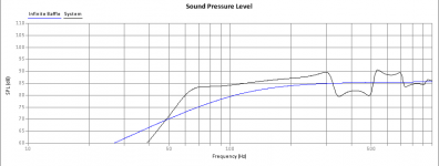
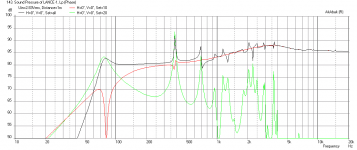
Here is what I get with Akabak - it seems to differ with respect to where the resonance dip and bass peak is and also the falloff in the LF. I wonder if it is because I am treating the actual vent radiator as located in the back offset vertically and rear firing? There is a baffle step loss as expected for a narrow 5in wide baffle that if compensated for, results in about an 80dB sensitive speaker. The results are very flat and IMO, an excellent design for the FF85WK. Sticking other drivers in such as 3FE25, and random Tang Bands will not result in as nice of a flat profile.
Here is response without BSC in 4 pi space:

Here is response with 6ohm and 0,8mH BSC circuit:

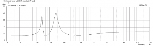
Here is Impedance:

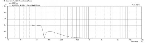
Hers is cone excursion:

Edit - Here is the response modeled without any consideration for physical locations of driver relative to vent, or reflections or baffle diffraction/losses:

Attachments
Last edited:
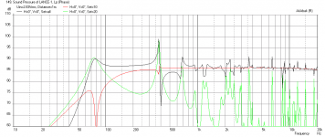
Possibly; also the fact that there's no damping in the AkAbak sim.
I usually only post co-incident plots on the forum to save time; for simple boxes they're ~'good enough' for an anechoic representation. Under practical conditions a shelving filter for step loss shouldn't be needed and I do not recommend adding one. It's a micro-monitor intended for use on desks or relatively close to boundaries; for e.g. as shown. The null at ~225Hz is floor-bounce; you can also see the effects of the higher harmonics that are killed by the two major bends (I haven't shown the effect to save time) and the specified damping -Martin's worksheets tend to understate the effects on higher frequencies in my experience / measurements -most likely due to variations in damping materials. As always, you can make this look pretty much however you want via placement, angle, furnishings etc., so YMMV as ever. To be honest, I'm rather fond of this little box -it's a nice performer for what it is (if I do say so myself) & the feedback has been positive.
I usually only post co-incident plots on the forum to save time; for simple boxes they're ~'good enough' for an anechoic representation. Under practical conditions a shelving filter for step loss shouldn't be needed and I do not recommend adding one. It's a micro-monitor intended for use on desks or relatively close to boundaries; for e.g. as shown. The null at ~225Hz is floor-bounce; you can also see the effects of the higher harmonics that are killed by the two major bends (I haven't shown the effect to save time) and the specified damping -Martin's worksheets tend to understate the effects on higher frequencies in my experience / measurements -most likely due to variations in damping materials. As always, you can make this look pretty much however you want via placement, angle, furnishings etc., so YMMV as ever. To be honest, I'm rather fond of this little box -it's a nice performer for what it is (if I do say so myself) & the feedback has been positive.
Attachments
Last edited:
Hope this isn't too much off topic.
Has anyone designed a TL cabinet for the Aura NS3-193-8A1. Something for a bookshelf application like the Lance or Harpoon.
I have a pair that are looking for a home and unfortunately I can't get my poor worn out old brain around all the math and sims that your guys are so good at. 😱
Has anyone designed a TL cabinet for the Aura NS3-193-8A1. Something for a bookshelf application like the Lance or Harpoon.
I have a pair that are looking for a home and unfortunately I can't get my poor worn out old brain around all the math and sims that your guys are so good at. 😱
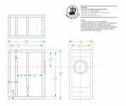
Since I was feeling benevolent (and already had a design roughed out which was in the ballpark for the Aura, so it didn't need much in the way of changing 😉 ): Redeye. The drawing is not to scale BTW; for simplicity & to save time, I simply used the Lance drawing Dave created & changed some of the text to suit.
As a general note, I favour the Lance design. In my opinion, the 85 is currently the pick of the drivers in this size bracket. Doesn't have quite as much on the bottom end as some, but these are 3in drivers we're talking about, so these things are relative. 😉 Not the cheapest to be sure, but it's worth it.
As a general note, I favour the Lance design. In my opinion, the 85 is currently the pick of the drivers in this size bracket. Doesn't have quite as much on the bottom end as some, but these are 3in drivers we're talking about, so these things are relative. 😉 Not the cheapest to be sure, but it's worth it.
Attachments
Last edited:
- Home
- Loudspeakers
- Full Range
- Woden Design 3" Box Designs, BabyLabs & more