Thanks! The T34B responds better to a different profile than the T34A as the dome heights are very different. I don't have and am unlikely to get a pair of T34B's to test.
You might be interested in Hificompass's small waveguide for the T34B, that would fit in your existing build and it is likely to be enough in an enclosure that has significant rounding, unless you want directivity control to lower frequencies.
https://www.diyaudio.com/community/threads/some-speaker-driver-measurements.317632/post-7734147
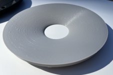
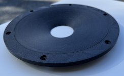
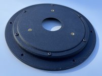
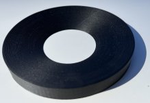
I found that three bolts for the wedge fixture wasn't really enough to make everything pull together evenly without any kind of lip, so I have made some with six. Some slicer changes and this is what they look like in ABS-GF and straight ABS. Of course they don't look any different behind the fabric but it will be interesting to see if there is any difference in sound or measurement from a smooth vs textured surface. I do like the the PETG-CF as a material but it has proved tricky to get a really nice top surface on it without some kind of lump or bump forming. Trying to scrape them off produces an ordinary looking lighter coloured scratch which kind of spoils the look if it is going to be on show. I had some succes in a test print to make a scarf seam that yould couldn't feel. It is still visible as change in colour wher it happens. Dissapointingly it did not work with the settings that make the rest of the waveguide surface look smoother.
Attachments

Did you heat the tweeter first ?I just use a small screw driver or tweezers, get in one of the holes of the grid and carefully lift it. You can use a pencil to form a lever to have more control. Just until it lifts a little, then do the next spot. The glue is not that strong.
Takes a minute to do.
Found a pic:
View attachment 1324001
[...]
Just as a reminder, the recommended procedure directly from Mr Malikov, put the driver in a oven set before at 60-70° (check the real temp before with instrument) for 5-7 minutes and voilà. I followed this procedure on several T25B and T34B
As far as I know the T25s don't have glue keeping the grille on, only the magnetic field.
Another piece of the puzzle arrived today a 38mm router bit from Aliexpress. Quite intimidating in person.
A similar item I got from Amana came with warnings about first removing as much material as possible using a 45 degree chamfer bit, never running it beyond 8000 rpm [1], feeding the material slowly, and culminating with AMYOYO: "Adios M***********, You're On Your Own".
At 8000 rpm the tip speed is about 37 meters / second, or 135 km/hr (~84 mph in Freedom Units), with a centrifugal acceleration of about 3100 g. It's possibly the single most terrifying piece of metal I own.
[1] I turn the Bosch down as far as it'll go, which seems to be adequately slow.
The T25's I have (which are relatively recent) do have the grill glued on. It is hard to take a picture of but you can see it in the groove. It would take quite some force to lever it off. When the glue was heated on the T34A it was very easy to lift the grill off with a wooden skewer.As far as I know the T25s don't have glue keeping the grille on, only the magnetic field.
I agree that working a large router bit is very intimidating.At 8000 rpm the tip speed is about 37 meters / second, or 135 km/hr (~84 mph in Freedom Units), with a centrifugal acceleration of about 3100 g. It's possibly the single most terrifying piece of metal I own.
I finally bought the big Makita router for my 25/32mm radius router - and that feels WAY more save now as the cheap one I used before. Has a precise speed control with lots of power. Going through MDF with the 25mm takes 2 turns, could be done with one when moving slowly.
But I found routers in the 100,- price area which seem to have good quality. These routers are the limit where cheap tools are not only expensive, they get seriously dangerous.
All T25 I built with had some glue to fix the grids. But it's not very strong, I never heated it to remove the grill.
But I found routers in the 100,- price area which seem to have good quality. These routers are the limit where cheap tools are not only expensive, they get seriously dangerous.
All T25 I built with had some glue to fix the grids. But it's not very strong, I never heated it to remove the grill.
Do a search for Ath-Dome in mabat's horn thread, the basic scripts are there, you can modify them for the dimensions of your driver. The depth of the waveguide needs to be shallow, mine is 16mm and the coverage angle wide, this one is 70 degrees. I'm not posting STL files of the waveguide, but with a different driver I'm not sure it would help you anyway. Soft domes are hard to simulate with BEM, when the dome stops being pistonic the simulation can also break down. The waveguide may not perform in reality the way it was predicted to.
Greatings @fluid and Merry Christmas!
Reading with great anticipations, And am curious how things are progressing 😊
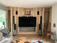
I am thinking on using the WG in an in-wall solution with Purifi woofers - and maybe with M74T-6 as part of the project. This is as far as built has come. At the arrows there are two woofers in each location for the very low bass.
There will be a total of 8 woofers in closed and actively compensated design for under 60Hz with extension down to 10Hz.. Right besides where speakers are temporary placed is where the mains will go. The wall is ”toed-in” 30 degrees here.
Electronics is hidden behind the TV which is on a wallmount that can be pulled out. Once done, it should more of less have the look of a standard wall, but with this ”toe-in” added. On topp there will be 15mm plywood followed by drywall, glued abd screwed.
The setup is a normal living room and purpose is music/movies for family. I am probably the only one that may have a critical listening session once in a while. But we all enjoy quality in sound reproduction and low distorsion.
Do you think your WG will have its place here?
Reading with great anticipations, And am curious how things are progressing 😊
I am thinking on using the WG in an in-wall solution with Purifi woofers - and maybe with M74T-6 as part of the project. This is as far as built has come. At the arrows there are two woofers in each location for the very low bass.
There will be a total of 8 woofers in closed and actively compensated design for under 60Hz with extension down to 10Hz.. Right besides where speakers are temporary placed is where the mains will go. The wall is ”toed-in” 30 degrees here.
Electronics is hidden behind the TV which is on a wallmount that can be pulled out. Once done, it should more of less have the look of a standard wall, but with this ”toe-in” added. On topp there will be 15mm plywood followed by drywall, glued abd screwed.
The setup is a normal living room and purpose is music/movies for family. I am probably the only one that may have a critical listening session once in a while. But we all enjoy quality in sound reproduction and low distorsion.
Do you think your WG will have its place here?
Attachments

Merry Christmas to you too 🙂
I am afraid that absolutely no progress has been made.
The waveguide in this thread is meant to be used with a reasonably low crossover point to a 6.5" woofer or similar in a freestanding enclosure. Those were the simulation conditions. It could work in a 2pi baffle wall, but I haven't simulated it in those conditions to know what the response would be. There may be a slightly different curve that would work better in a 2pi situation.
This waveguide is really quite large to mate with an M74. I did create a very small waveguide that is the same size as the faceplate that does not do a great deal but it does smooth the directivity a little over the bare driver on its own. That was simulated in 2pi.
You can find the STL file here, it worked for someone who printed it but I have never actually printed it myself.
https://www.diyaudio.com/community/...uides-for-cnc-3d-printing.318190/post-7171815
Thanks @fluid!
I am going back and fourth adding the m74, or just keep it ”simple” with a ”kind of” 2,5 way using Purifi 6,5” woofers.
I think I read somewhere that you have helped some member here with a wg for T25 towards M74 for a crossover at 3KHz, care to share that? It would be highly appriciated!
I think I need to make a few test baffles to see what options I prefere.
3- way with M74 and T34, 3-way with M74 and T25 or 2,5-way with T25 or T34.
Never done an in-wall project before so I am kind of having really fun here!
Last edited:
Yes I did. I am in the UK for the next few weeks so I don’t have access to my files.I think I read somewhere that you have helped some member here with a wg for T25 towards M74 for a crossover at 3KHz, care to share that? It would be highly appriciated!
It was a very simple section of a circular radius. That can be drawn fairly easily in a CAD program. I never made a full stl as they needed to adapt the curve to an existing cutout. It is basically the same as the small T34A one linked above just using a different starting point for the dome radius.
Then you are closer then normal right now, no worries, I am not in a hurry, but would be happy to get something to test.Yes I did. I am in the UK for the next few weeks so I don’t have access to my files.
I need to work a little on the rest of the house before I can have fun for real. Reason for the project with the wall started was that ventilation needed access from attic to basement. So I think its more or less 3-4 untill the Bliesma mid and tweeter arrives and until then I will work on rest of the house. It’s getting closer, but until that is done at least I have 4 of the 8 subs in play.
In case you missed it, this might be what you wanted.Then you are closer then normal right now, no worries, I am not in a hurry, but would be happy to get something to test.
https://www.diyaudio.com/community/threads/t25a-simple-waveguide-profile.423131/#post-7912455
In an effort to move this project out of neutral I have decided to try a different direction. I am not going to be cutting wood in my shed for the next few months due to heat and humidity.
But I do have a 3D printer sitting idle... A recent video posted by vineeth got me thinking. Why don't I try 3D printing the cabinet. I have seen some pretty average attempts at this in the past as well as some more impressive efforts like those from @chargedcapacitor.
I will probably redsign the cabinet shape to make it easier to print and just because.
If anyone has any thoughts (preferrably through experience) on ways or ideas to make 3D speakers cabinets I would be interested before I dive too deep into the design.
- Home
- Loudspeakers
- Multi-Way
- Wide Directivity 2 way compact Speaker T34A Waveguide and Purifi 6.5 Aluminium