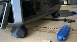
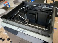
I have finished printing the modifications for the K1 Max and so far so they have worked out well. The riser relocates the filament runout sensor and lets the feed tube go straight out of the side down to the filament dryer. There is a guide tube that rotates so the feed tube does not attach to the drag chain and being higher there is less of a bend towards the extruder. With this setup I have been able to print a few small parts out of the ABS Glass Fibre filament successfully. The squash ball feet do seem to do something positive. I have the printer on a rolling tool chest and before there was regualrly quite a loud metallic shaking sound when the printer set off something in the structure of the tool trolley. Now it is much less frequent abd quieter so for the cost of four squash balls it was worth it. In the picture of the feet you can just make out an odd shaped piece of black plastic next to the bit driver. This lifts up the drag chain a few millimetres and stops it from rubbing on the linear rods.
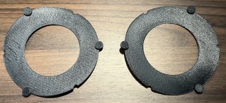
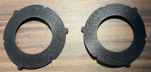
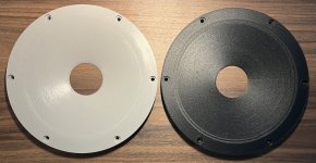
In one image you can see two small rings printed in PETG CF on the upper side and ABS GF25 on the lower side. With Orca Slicers seam gap the seam is visually quite obvious on the PETG CF, random seam hides much better in the ABS GF25 which looks much more the look I was expecting the Carbon PETG to have.
A waveguide in ABS GF 25 is printing now so fingers crossed that looks good when it is done.
Attachments


Well Fluid, it's not the first time that a squash ball has helped out an Aussie... Adam Gilchrist (one of my favorite players) had a squash ball inside his glove while batting in the ICC World Cup 2007 Final, and blasted 149 runs off 104 balls... 🙂
I have pondered if the stability of the foundation on which a 3D printer is placed has any impact on the print results... what say you...?
//
//
To a certain extent it does, the more stable the platform the better within reason. With Klipper based printers much is compensated through input shaping to counteract the resonances and that makes it less susceptible to issues from the platform. Printing fast and using gyroid or similar infills puts the input shaping to the test.
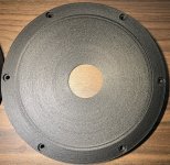
The ABS-GF waveguide finished printing and I don't think it looks too bad. No variable layer height so it printed faster too. The surface is rough but that is kind of the point. I have tried to light the pictures as a worst case scenario. The pure ABS is the choice if a super smooth flat finish is desired, but for those that just want to bolt it in and not mess around the Glass Fibre does the job. I printed some spacers in the GF filament to see what it was like. Being only a single layer it has warped quite a lot but is still very strong. The top side is a little rough, the bed side is what sits against the waveguide and looks much better. I think the PETG-CF was the winner for this purpose.
Attachments
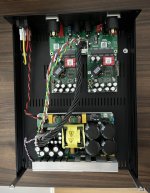
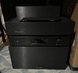
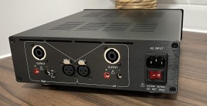
I decided to buy a Ghent case to house my Purifi Eval1 amp board that has been sitting in a cupboard for a long time. This is to DIY amp building what IKEA is to furniture, but it was done in 2 hours instead of many days. The case is certainly more WAF friendly compared to the rest of the stack. The quality of the internal cabling looks to have gone up over time, shame about the only nick on the anodizing being right on the top edge, nothing a felt tip pen can't hide though 🙂
Attachments

Same for me at home, but then 3 of those amps. ;-)
And a okto Dac8 Pro, and 2 fanless computers, it still fits in the cabinet, and actually looks more organized.
And a okto Dac8 Pro, and 2 fanless computers, it still fits in the cabinet, and actually looks more organized.
Last edited:
I am not following you here... I don't have deep knowledge of 3D printing, so I think I am missing something. Would an ABS printed waveguide be difficult to bolt (screw) into a recess on a plywood box?The surface is rough but that is kind of the point. I have tried to light the pictures as a worst case scenario. The pure ABS is the choice if a super smooth flat finish is desired, but for those that just want to bolt it in and not mess around the Glass Fibre does the job.
Is surface roughness a concern in a waveguide? I have always assumed that bumps and irregularities near a tweeter could have a measurable impact down to a level of 1/10 * wavelength, which for 20k is about 1.7 mm... A surface roughness of 1.7 mm would be quite rough, and most 3D parts I have seen would seem to be well below that.
Thanks for pointing out the Ghent product. I was not aware of that.
j.
No it would not. This is about the aesthetics of a waveguide straight off the printer. The textured finish of the Glass Fibre filament hides the layer lines better and can result in a finished product straight away. The pure ABS looks a little bit less "finished" when it comes straight of the printer, but the plastic is very easy to work to take the blemishes out and leave a very smooth finish that would be ideal for filling, priming and painting. I suspect that will ultimately be my preference but it is quite a bit more work.I am not following you here... I don't have deep knowledge of 3D printing, so I think I am missing something. Would an ABS printed waveguide be difficult to bolt (screw) into a recess on a plywood box?
The glass fibre was printed with 0.16mm layers, I doubt the roughness be be any more of a variation than 0.3mm. I wouldn't expect this to have any effect on the measurements but it is something I will look at when I get to measuring.Is surface roughness a concern in a waveguide? I have always assumed that bumps and irregularities near a tweeter could have a measurable impact down to a level of 1/10 * wavelength, which for 20k is about 1.7 mm... A surface roughness of 1.7 mm would be quite rough, and most 3D parts I have seen would seem to be well below that.
You are welcome 🙂Thanks for pointing out the Ghent product. I was not aware of that.
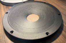
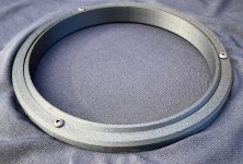
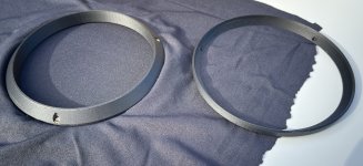
On the first generation of succesful prints the waveguide is 16mm deep at the mounting flange. I did this for simplicity and strength but it means that the panel thickness needs to be more to mount it. The very gradual curve of the waveguide doesn't leave a lot of material to work with. I am trialling a new mounting scheme where the mounting flange is a separate part which allows it to be printed flat on the bed without support material. There is then a mechanical lock where the flange and main waveguide body fit into each other with a wedge piece that connects to the waveguide body and fix the mounting flange in place. I printed it with a small gap between the two so I could stretch some grille fabric over and wedge it in the gap. In this configuration all that is seen is the nice textured finish off the bed and a round section of cloth. Three more heat set inerts are used to bolt the parts together. So far I like this option as it is does not need any finishing effort and leaves a very clean look and some inbuilt protection for the driver. I tried out the Hilbert Curve option on the bottom surface which imparts a subtle pattern. Normally it takes an unreasonable amount of time to print so I don't bother but in this configuration it will be seen and thought it might be interesting.
The new filament path modifications seem to have fixed the issue was having before printing abrasive filaments reliably.

The new filament path modifications seem to have fixed the issue was having before printing abrasive filaments reliably.
Attachments


Very cleverly made Duncan ! as usual I should add. I dare to see the end result (polar map) on the T34A...
The measurements will come but getting everything ready to make good ones is a large chunk of shed time that requires some juggling to get. No one else in my house appreciates audio, the Sonos makes an acceptable noise so why do I need to make my own...
Almost same with my wife, except that now after 3 months she begins to miss good quality sound, a nice change ;-)
What DI are you aiming at for the tweeter section, and why did you decide for a symmetrical waveguide that got higher total DI than an asymmetric?
I was aiming for smooth wide directivity as high in frequency as possible. I didn't have a DI target in mind and I haven't actually simulated the DI directly as a curve. An asymmetric waveguide will always have a more sharply rising SPDI at high frequencies from the narrower wall angle affecting the vertical response. That is the opposite of what I was trying to achieve.What DI are you aiming at for the tweeter section, and why did you decide for a symmetrical waveguide that got higher total DI than an asymmetric?
This project looks great and I'm eagerly awaiting measurements. I recently did a build with a Purifi 6.5" paper cone and Bliesma T34B tweeter. I love it but ultimately I really wish I had a waveguide on the tweeter because I just couldn't get the off-axis to be as good as I wanted. So now I'm going to wait for your measurements and then try to get you to make some waveguides for me!!!!!
- Home
- Loudspeakers
- Multi-Way
- Wide Directivity 2 way compact Speaker T34A Waveguide and Purifi 6.5 Aluminium