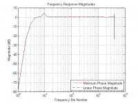
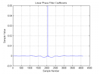
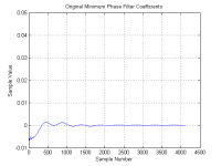
I usually get paid for things like this, but for now I'll let that pass and just say that three pictures are worth a thousand words. Note the vertical scales on the waveforms, and also that there is a peak at sample "0" in the minimum phase plot with value near 1.0.If you can take the convolution steps on the minimum-phase FIR file i attached and provide your linear-phase version,
then I will run a transfer function on the two versions.
No better proof positive than that, i think.
Attachments
Nopa, it's 512.It’s the same as 2048 at 48k (not 512)
The reason is you are using more taps before the impulse peak, than centering would... thereby having greater control on phase.But yeah , when it’s all you got , centering I the 9ms area adds a whole bunch more phase control….
Yes, 10.66ms is 1024 samples at 96k. And all there is. So see how 9ms is closer to the end ?But to your previous point, it won’t let me go past I think 10.66ms iirc , idk why, maybe fir is simply shorter then 10.33ms is the max , where exact centering takes me to 5.33ms, so yeah a little past the center of ir seems to give better phase control….
It is wavelength of the frequencies and how much time it takes to alter the phase of the wavelengths, with lower freq taking longer / needing longer FIR time.At the lower frequencies…. And thinking what you said about the first half being iir, it made sense a little
I thought it had something to do with the wavelength of the frequencies, but what your saying makes me think the length of the fir….. so thanks.
Here's a good article on # taps. And it's definitely worth going thru all the articles in the series.
https://www.prosoundtraining.com/2016/05/20/fir-ward-thinking-part-5/

Thx for that.I usually get paid for things like this, but for now I'll let that pass and just say that three pictures are worth a thousand words. Note the vertical scales on the waveforms, and also that there is a peak at sample "0" in the minimum phase plot with value near 1.0.
I've been talking about real FIR files, with tap limitations.
Do the graphs you show reflect tap limitations?
Or are they pure math based on the trace of the FIR file I posted ?
Seems like they must be, because I simply cannot reconcile magnitude response being the same with real FIR files.
Can you provide a linear phase FIR file that you made from the convolution steps outlined, that I can load into a processor?
Like said, I can run a transfer function one against the other, in about 30 seconds 🙂
Hi @pos thanks for looking,
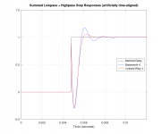
@gberchin shared a paper with us of a Matched-Delay Subtractive Crossover Pair With 4th-Order Highpass Slope. When the two are combined (LP filter and HP filter) there's no ringing. See this summation example:

This paper he shared with us trough PM, see this post:
In a later post he shared his continuous development of his work here: https://www.diyaudio.com/community/...nearization-by-fir.393435/page-6#post-7213543
I believe this crossover type would be easiest to implement using FIR files, so that made me think of your RePhase program. If there's no objection from @gberchin to do this. And you'd be willing to work out the implementation. We can hope though, right? 🙂
@gberchin shared a paper with us of a Matched-Delay Subtractive Crossover Pair With 4th-Order Highpass Slope. When the two are combined (LP filter and HP filter) there's no ringing. See this summation example:
This paper he shared with us trough PM, see this post:
(actually, a PM was enough as the paper could be attached to a DM)I'll be happy to. Anybody who's interested, just send me a private message with your email address. I'll send you the latest version of the paper.
In a later post he shared his continuous development of his work here: https://www.diyaudio.com/community/...nearization-by-fir.393435/page-6#post-7213543
I believe this crossover type would be easiest to implement using FIR files, so that made me think of your RePhase program. If there's no objection from @gberchin to do this. And you'd be willing to work out the implementation. We can hope though, right? 🙂
I have no idea what you're talking about. You choose to disbelieve the truth even when the proof is presented to you. I'm finished.I've been talking about real FIR files, with tap limitations.
Do the graphs you show reflect tap limitations?
Or are they pure math based on the trace of the FIR file I posted ?
Seems like they must be, because I simply cannot reconcile magnitude response being the same with real FIR files.
I have no objection, as long as the inventor is acknowledged.If there's no objection from @gberchin to do this. And you'd be willing to work out the implementation. We can hope though, right? 🙂
Nopa, it's 512.
The reason is you are using more taps before the impulse peak, than centering would... thereby having greater control on phase.
Yes, 10.66ms is 1024 samples at 96k. And all there is. So see how 9ms is closer to the end ?
It is wavelength of the frequencies and how much time it takes to alter the phase of the wavelengths, with lower freq taking longer / needing longer FIR time.
Here's a good article on # taps. And it's definitely worth going thru all the articles in the series.
https://www.prosoundtraining.com/2016/05/20/fir-ward-thinking-part-5/
I was thinking backward , your right 512 (my bad)
That was an excellent article, thank you! Send more please ! 😃
I’m done mucking up thread , I’m reading tho , you guys have done good stuff…. Would love to try that equal phase crossover….
Last edited:
@gberchin shared a paper with us of a Matched-Delay Subtractive Crossover Pair With 4th-Order Highpass Slope. When the two are combined (LP filter and HP filter) there's no ringing.
Thanks for the info.
I am probably missing something and need to take the time to read the thread and paper, but if implemented using FIR what is the advantage compared to a pair of 4th order LR filters, which will also sum with no ringing.
This is the advantage:... if implemented using FIR what is the advantage compared to a pair of 4th order LR filters, which will also sum with no ringing.
Attachments

Well, if you're comparing one FIR linear-phase perfect-reconstruction crossover to another, then it comes down to just a couple of items: number of coefficients and transition-band slopes. Frankly, the difference in the number of coefficients is probably not worth arguing about. The Gaussian-derived MDS lowpass filter has much steeper lowpass slope, and similar highpass slope in its 4th-order highpass version (there is also a much simpler 2nd-order highpass version).Sorry I meant to say linear-phase LR
The MDS crossover also has the option of using an IIR Bessel LPF instead of a FIR Gaussian LPF, while still achieving perfect reconstruction and approximating linear phase. This may lead to some implementation advantages.
In rePhase there is the "reject high" linear-phase filter type that has a similar behavior.The Gaussian-derived MDS lowpass filter has much steeper lowpass slope, and similar highpass slope in its 4th-order highpass version
Sure, being able to use IIR is a clear benefit.The MDS crossover also has the option of using an IIR Bessel LPF instead of a FIR Gaussian LPF, while still achieving perfect reconstruction and approximating linear phase. This may lead to some implementation advantages.
Oh my God, that theory is really gross, man.Taps before the impulse peak work on altering the time domain (phase).
Taps after the impulse peak work on altering the frequency domain.
So Impulse peak at start of FIR filter= minimum phase / IIR replication; with all samples working on frequency magnitude alteration, and none on phase.
Impulse peak at end of FIR = maximum phase; with all samples working on phase alteration, and none on frequency.
And impulse peak at center of FIR = linear phase; with one-half of the samples working on phase, and one-half working on frequency.
Actually, I think it's more like negative time/frequency before the peak and positive time/frequency after the peak. Thus, when both look different, the filter has group delay (phase distortion). And, yes, there's negative frequency in signal processing, and it exists for mathematical convenience.
Sorry if i offended you with further questions. And sorry if it wasn't easily clear that what i was hoping for was an actual FIR file, wav or csv etc, that I could load and test.I have no idea what you're talking about. You choose to disbelieve the truth even when the proof is presented to you. I'm finished.
I do 98% of my research using measurements of physical processors.. I find measurements of useable processing often have constraints and limitations not seen in computer simulations. And then I try to learn why.
That's what happened with my opening post/error....I learned not having bandwidth to zero Hz, making a mistake in phase-linearizing a system hpf, clock sync issues, and AD/DA conversions kept my measurements from looking clean like sims.
Thank you for the time you put in with me....
Mark100,
I've MATLAB installed as well and just processed your impulse response of length 4096 and fs =48kHz. I am attaching two files MinPhase and LinPhase obtained by convolution of the your original test file with itself and a reversed version of itself respectively.
EDIT: There was an error in the code and I've replaced the files.
Attachments
Last edited:
Oh my God, that theory is really gross, man.
Yeah it is !! But it works (for me) better than you might think.
I like that description....."negative time/frequency before the peak and positive time/frequency after the peak".....much better than my depictionActually, I think it's more like negative time/frequency before the peak and positive time/frequency after the peak. Thus, when both look different, the filter has group delay (phase distortion). And, yes, there's negative frequency in signal processing, and it exists for mathematical convenience.
Thank you very much for those! 🙂 we cross-posted i see...Mark100,
I've MATLAB installed as well and just processed your impulse response of length 4096 and fs =48kHz. I am attaching two files MinPhase and LinPhase obtained by convolution of the your original test file with itself and a reversed version of itself respectively.
EDIT: There was an error in the code and I've replaced the files.
Just tried them.....something appears amiss.
I'm measuring that both your versions show a FIR time delay of 85.29ms, which is about 2 samples short of the entire 4096 taps@48kHz filter length.
The min phase FIR I posted, with impulse center at 1 sample , has essentially no delay.
I'd expect a lin phase version, with impulse center at 2048 samples to have 42.67ms delay
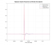
edit: here's a transfer function using the min phase version i posted as reference, and a lin phase version i made shifting impulse to center, as measurement.
It has the lack of frequency resolution, I am used to seeing in such comparisons.
Last edited:
I know. And I was trying to show you that it could be done, thereby encouraging you to do it yourself. It's a carryover from the old comp.dsp days, where there was an unwritten rule that we would help students with their homework, but not do their homework for them.Sorry if i offended you with further questions. And sorry if it wasn't easily clear that what i was hoping for was an actual FIR file, wav or csv etc, that I could load and test.
That will produce the square of the filter response, not the filter response.I am attaching two files MinPhase and LinPhase obtained by convolution of the your original test file with itself and a reversed version of itself respectively.
- Home
- Loudspeakers
- Multi-Way
- Why not IIR filters + a global phase linearization by FIR