Let me try to simplify this as much as I can (at the risk of oversimplifying). I'm trying to be as kind as I can here, but thus far you're just not getting it:The amount of FIR time (#taps@sample rate) after the impulse peak is the primary factor in determining frequency resolution,
and the amount of FIR time before the impulse peak is the primary factor in determining time resolution.
There is only one thing that affects resolution in the frequency domain, and that is duration in the time domain. There are multiple mathematical definitions of duration, and multiple associated mathematical definitions of resolution, but they all share one thing in common: the reciprocal relationship between duration and resolution.
There is only one thing that affects phase linearity, and that is symmetry in the time domain. If the impulse response is symmetrical, then the phase response is linear, and vice-versa. The symmetry may be even or it may be odd; either way if the symmetry is present then the phase is linear. If the symmetry is not present, then the phase is not linear.
There are infinitely many impulse responses that all produce exactly the same frequency response magnitude; they differ only in their phase responses.
It is easy to turn a minimum phase response into a linear phase response; you've seen it done here at least a couple of times. It is far more difficult to turn a linear phase response into a minimum phase response; Oppenheim & Shafer offer an approximation technique.
thank you !Let me try to simplify this as much as I can (at the risk of oversimplifying). I'm trying to be as kind as I can here, but thus far you're just not getting it:
Yes.There is only one thing that affects resolution in the frequency domain, and that is duration in the time domain. There are multiple mathematical definitions of duration, and multiple associated mathematical definitions of resolution, but they all share one thing in common: the reciprocal relationship between duration and resolution.
I understand that F=1/T, where F is frequency resolution, and T is time in seconds.
What I think to be true, is the "effective" T in a FIR filter, is the time duration of the samples that are after the impulse peak.
My thinking comes from articles such as this one. https://www.prosoundtraining.com/2016/05/20/fir-ward-thinking-part-5/
And a minimum phase FIR example of frequency resolution.

The article goes on to contrast the minimum phase resolution with the same size filter used for linear phase.
"By using 1/2 of the filter length for “negative relative time” corrections, the frequency resolution of the filter is halved. For example, a 1024 tap min phase FIR has 47.6 Hz frequency resolution. The same tap length for a linear phase FIR has a frequency resolution of 95.2 Hz, since up to one-half of the filter length is reserved for phase equalization."
I've no doubt with your expertise, that can find a number of points in the article that are either in technical error or need restating.
But setting those aside, is the article pragmatically correct? Frankly, that's all I care about....simple real-world, how to make stuff work.
Yes again. I understand well that symmetry, impulse centering, is required for linear phase.There is only one thing that affects phase linearity, and that is symmetry in the time domain. If the impulse response is symmetrical, then the phase response is linear, and vice-versa. The symmetry may be even or it may be odd; either way if the symmetry is present then the phase is linear. If the symmetry is not present, then the phase is not linear.
As said earlier, I have made FIR files for a sub to main xover for live-sound use, when propagation delay is an issue.
So I can't use my standard linear-phase xovers, and I move impulse closer to start to reduce delay.
For higher order xovers in the 80 to 100Hz range, and 48KHz tap counts between 4-16K, I have found that moving the impulse closer to start,
turns into a juggling act between how well the filter holds true to the target xover response, versus how well it holds true to maintaining linear phase response.
Which is as expected, from gaining more effective filter time by placing impulse closer to start, and loosing the symmetry needed for linear phase.
Of course.There are infinitely many impulse responses that all produce exactly the same frequency response magnitude; they differ only in their phase responses.
Yep, easy. Certainly so with sufficient taps@sample rate. (effective FIR time)It is easy to turn a minimum phase response into a linear phase response; you've seen it done here at least a couple of times.
Why on earth would anyone want to do that? LolIt is far more difficult to turn a linear phase response into a minimum phase response; Oppenheim & Shafer offer an approximation technique.
I understand that F=1/T, where F is frequency resolution, and T is time in seconds.
That is a trivial definition of "resolution". What is true is that the frequency bin spacing in a Discrete Fourier Transform is the reciprocal of the time spanned by the samples being transformed (whether those samples are nonzero or not), and that the time domain sampling period is the reciprocal of the sampling frequency.
There are more sophisticated ways to determine duration and resolution of real signals. They often use moments are are therefore similar to statistical methods like variance and standard deviation. As I mentioned once before, simply adding a bunch of zero-valued samples to the end of a time-domain waveform doesn't increase frequency resolution.
What I think to be true, is the "effective" T in a FIR filter, is the time duration of the samples that are after the impulse peak.
No, no, no, no, no! There is no concept of "before" or "after" in measurement of the duration of an impulse response (coefficients of a FIR filter). You can create a minimum-phase impulse response, with its peak near the beginning, truncate its length to something manageable, and measure its duration. You can then reverse the order of that impulse, so that the peak is near the end, and its duration will be identical to that of the original "forward" impulse.
By using 1/2 of the filter length for “negative relative time” corrections, the frequency resolution of the filter is halved. For example, a 1024 tap min phase FIR has 47.6 Hz frequency resolution. The same tap length for a linear phase FIR has a frequency resolution of 95.2 Hz, since up to one-half of the filter length is reserved for phase equalization."
That would only be true if one were to convert a linear-phase filter into a minimum-phase filter by simply zeroing the first (or second) half of the filter. That is not how it's done. A minimum-phase filter and its linear-phase equivalent have exactly the same length and duration -- they must, since they produce identical frequency response magnitudes. You've seen some examples of that right here.
I don't know what the author of that article was alluding-to, but that's not how it works when done properly.
As said earlier, I have made FIR files for a sub to main xover for live-sound use, when propagation delay is an issue.
So I can't use my standard linear-phase xovers, and I move impulse closer to start to reduce delay.
Exactly how do you "move the impulse closer to the start"? You can't just throw-away samples before the peak and expect the response to remain the same.
Why on earth would anyone want to do that [convert a linear-phase filter to minimum-phase]? Lol
For exactly the reason that you stated -- to reduce delay.
How do you know that's not how it works when done properly, ......if you don't know what the author of that article was alluding to?I don't know what the author of that article was alluding-to, but that's not how it works when done properly.
Not trying to be a smart-****....just sayin....
Exactly how do you "move the impulse closer to the start"? You can't just throw-away samples before the peak and expect the response to remain the same.
In the FIR generator, I simply choose what sample within the constant file size to place impulse peak centering.
Like I described in the sub-to-main xover tug of war, between frequency response target matching, and maintaining linear phase.
That was meant to be a joke 🙂For exactly the reason that you stated -- to reduce delay.
I sense I haven't been able to communicate to you in a way that allows you hear what I'm trying to say. My fault, not yours, due to large differences in vocabulary and depth of understandings.
You've been very generous with your time and comments. I'll not ask any more of your time. Thanks again and best.
Well, bring it if you want, we'll see what happens.Now, anybody think that success will be achievable if we cut taps in half, (or hold tap count and raise the sampling rate)?
Or move the PEQ from 100Hz to 50Hz, or raise the PEQ's Q from 6 to say 10? Or increase the order of the high-pass? Or add more PEQ's, both boosts and cuts?
Point being the test wasn't that hard, and I think optimization can only go so far.
In the end isn't it just a matter of having sufficient taps for the desired filter set. Wheter the filter set be for minimum, linear, or mixed phase?
mark100 said:
Now, anybody think that success will be achievable if we cut taps in half, (or hold tap count and raise the sampling rate)?
Or move the PEQ from 100Hz to 50Hz, or raise the PEQ's Q from 6 to say 10? Or increase the order of the high-pass? Or add more PEQ's, both boosts and cuts?
Point being the test wasn't that hard, and I think optimization can only go so far.
In the end isn't it just a matter of having sufficient taps for the desired filter set. Wheter the filter set be for minimum, linear, or mixed phase?
And make that the only filter up for comparison, for further simplification.
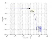
So nothing but a min-phase 50Hz, Q=6, +5dB PEQ.
Using same size file as previous, 4096 taps@48kHz.
Even with impulse centering at the start and extensive optimization, 4k taps can't quite track the PEQ without error.
(Output gain is lowered 1dB to preclude clipping)

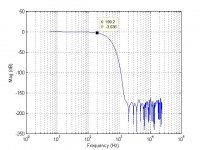
Moving impulse to center.

That the best rePhase's extensive optimization could do with the taps available.
Here's the FIR file with impulse at start.
If you can move impulse to center and match its magnitude response, that would be really cool. (same size file of course)
Now, anybody think that success will be achievable if we cut taps in half, (or hold tap count and raise the sampling rate)?
Or move the PEQ from 100Hz to 50Hz, or raise the PEQ's Q from 6 to say 10? Or increase the order of the high-pass? Or add more PEQ's, both boosts and cuts?
Point being the test wasn't that hard, and I think optimization can only go so far.
In the end isn't it just a matter of having sufficient taps for the desired filter set. Wheter the filter set be for minimum, linear, or mixed phase?
Ok sure, I'll just pick the first one from the list....move the PEQ from 100Hz to 50 Hz.Well, bring it if you want, we'll see what happens.
And make that the only filter up for comparison, for further simplification.
So nothing but a min-phase 50Hz, Q=6, +5dB PEQ.
Using same size file as previous, 4096 taps@48kHz.
Even with impulse centering at the start and extensive optimization, 4k taps can't quite track the PEQ without error.
(Output gain is lowered 1dB to preclude clipping)
Moving impulse to center.
That the best rePhase's extensive optimization could do with the taps available.
Here's the FIR file with impulse at start.
If you can move impulse to center and match its magnitude response, that would be really cool. (same size file of course)
Attachments
I would say that even your better plot above is very poor. 4096 taps is too short of an impulse to accurately reproduce the desired response at 50Hz without artifacts or errors. Increase the number of taps in stages by 2x each time up to at least 48k taps and you will see how the accuracy changes with filter length.
The problem is that low frequency features require lots of FIR taps to be accurately reproduced by the filter. If your PEQ was centered at 1kHz you can then use a much shorter length e.g. in the several thousands.
The problem is that low frequency features require lots of FIR taps to be accurately reproduced by the filter. If your PEQ was centered at 1kHz you can then use a much shorter length e.g. in the several thousands.
So nothing but a min-phase 50Hz, Q=6, +5dB PEQ.
Using same size file as previous, 4096 taps@48kHz.
......
If you can move impulse to center and match its magnitude response, that would be really cool. (same size file of course)
Better than RePhase I think, isn't it ?
In my opinion, an FIR copy of an IIR filter is a sheer waste of resources when the IIR filter could be implemented rather easily using recursive methods, with fewer coefficients and storage requirements. It is a bit like taking the photograph of a page in a book and saving it as an image, vs. saving the contents as text, just a simple thought.
Attachments
Last edited:
I would say that even your better plot above is very poor. 4096 taps is too short of an impulse to accurately reproduce the desired response at 50Hz without artifacts or errors. Increase the number of taps in stages by 2x each time up to at least 48k taps and you will see how the accuracy changes with filter length.
Yep, too few taps for the task.
That's a good point/method for finding minimum taps needed, for any who are following along nd don't already know it.
Yep again.The problem is that low frequency features require lots of FIR taps to be accurately reproduced by the filter. If your PEQ was centered at 1kHz you can then use a much shorter length e.g. in the several thousands.
In practice, i've found tap count generally needs to double with each octave decrease that's included in the FIR.
And I'll re-quote myself,
"In the end isn't it just a matter of having sufficient taps for the desired filter set. Whether the filter set be for minimum, linear, or mixed phase?"
Because of the efficiency of the DFT as the sequence length increases it is usually a safe bet and a good rule of thumb to err on the side of having more taps in your filter than you think you need.
Better than RePhase I think, isn't it ?
Yes it is ! Nice.
here's REW comparing the impulse strart version i posted in green,
and your impulse centered version in red.
I totally agree with that. I use true IIR, as preconditioning filters in front of low frequency FIR work.In my opinion, an FIR copy of an IIR filter is a sheer waste of resources when the IIR filter could be implemented rather easily using recursive methods, with fewer coefficients and storage requirements. It is a bit like taking the photograph of a page in a book and saving it as an image, vs. saving the contents as text, just a simple thought.
It took me a while to realize that using FIR for minimum phase / IIR work, is yes IIR, but with only the frequency resolution of the FIR filter.
That realization, and the desire to reduce latency while still using FIR....is what led me to seeing how effective frequency resolution increases with impulse closer to start (given constant file size.)
Anyone else having problems opening the attached .zip file? Both Windows and 7-zip complain that it's not an archive file.View attachment 1124674
Better than RePhase I think, isn't it ?
In my opinion, an FIR copy of an IIR filter is a sheer waste of resources when the IIR filter could be implemented rather easily using recursive methods, with fewer coefficients and storage requirements. It is a bit like taking the photograph of a page in a book and saving it as an image, vs. saving the contents as text, just a simple thought.

I'm limited to 16k taps @ 48kHz per channel, due to choice of processing hardware.Because of the efficiency of the DFT as the sequence length increases it is usually a safe bet and a good rule of thumb to err on the side of having more taps in your filter than you think you need.
However, with IIR preconditioning for low end work, it seems more than sufficient.
To illustrate the need for more taps to handle the 50 Hz PEQ and fully match IIR.
Purple: pure IIR
(following used rephase 'extensive optimization', other than newvirus's as designated)
Blue: 8k taps and impulse at start
Green: 4k taps and impulse start
Red: 4k taps and impulse in center ala newvirus's optimization
Orange: 4k taps and impulse in center ala rePhase
Hey newvirus, you inspired me to make some more comparisons, with that nicer optimization of the 50Hz PEQ, 4k taps centered.
I went to my go-to FIR generator, FirDesigner, to see how its default output looks for 4K centered, ......to compare to yours.
(been using rePhase so anyone caring to, could duplicate what's posted)
Seems like whatever optimization you are doing, is quite similar to FirD's.
Red is your file.
The Blue trace is FirD with its default Cosine Tapered window.
Green, which lies even closer to your trace, is using Boxcar windowing.
Is boxcar what you used?
Is boxcar what you used?
Yes, rectangular windowing, the simplest of all.
To get back at the original question:
If one were to use IIR implementations with block reversal (somehow), he wouldn't need to worry about "taps", as the typical PEQ structures (for any Q-factor, gain, center) use only 2 or 4 delay blocks at most. Also, with double precision, the errors / complications related to the recursive implementation are also usually not a problem, not even at 192kHz. It was for this reason that I brought up block processing in the first place. Since the block size can be made small (<256 samples), the only remaining issue would be regarding the proper "stitching" of the processed blocks to avoid artifacts.
Like Charlie said above, there're two delays: One due to the computations and the other for satisfying causality, and since the latter cannot be violated by any method (including FIR). the only thing we can aim for is to minimise the former, which IIR filters are very good at, with very good response tracking of analogue filters, even to the lowest frequencies.
Last edited:
Here is an example from Stanford, math that I don't understand but the impulses are the same length and so are the magnitudes with a pretty steep filter.Point being the test wasn't that hard, and I think optimization can only go so far.
https://ccrma.stanford.edu/~jos/filters/Linear_Phase_Really_Ideal.html
It seems to me that you are looking at making rules based on how specific programs respond and I can understand as they do behave that way.
I found some of gberchin's previous articles kind of by accident but the FDLS algorithm seems to be very powerful.
https://www.iro.umontreal.ca/~mignotte/IFT3205/Documents/TipsAndTricks/PreciseFilterDesign.pdf
Example files attached
and there is a python version for those without Matlab
https://github.com/blair3sat/fdls
Attachments
Here're FIR copies of the Gaussian function (4096 pts) for anyone interested in trying Mr. Berchin's crossovers.
Attachments
Last edited:
Indeed it is, but in high-Q situations FDLS can sometimes be hit-or-miss.I found some of gberchin's previous articles kind of by accident but the FDLS algorithm seems to be very powerful.
Just a disclaimer: I did not write the Python version referenced there, so I cannot vouch for it -- though I have no reason to doubt its correctness. I have a Python version that I wrote myself -- though since I was just learning Python at the time I cannot vouch for its correctness, either 🙂. Send me a PM and I'll return either the Matlab/Octave or the Python version, or both.and there is a python version for those without Matlab
https://github.com/blair3sat/fdls
Oh, and there is also an allpass version of FDLS that allows you to design an IIR allpass filter with arbitrary phase response (within constraints). It can sometimes allow you to convert a nonlinear-phase filter into an approximately linear-phase filter. Written in Matlab/Octave. Again, PM for a copy.
@gberchin : In what form are the IIR coefficients produced? Is it as numerator and demoninator polynomials at the full overall degree, or factored into a product of some number of first and second order N and D? I am always concerned about stability for higher order rational polynomials ...Oh, and there is also an allpass version of FDLS that allows you to design an IIR allpass filter with arbitrary phase response (within constraints). It can sometimes allow you to convert a nonlinear-phase filter into an approximately linear-phase filter. Written in Matlab/Octave. Again, PM for a copy.
- Home
- Loudspeakers
- Multi-Way
- Why not IIR filters + a global phase linearization by FIR