I just happen to have that information! The 8th-order Bessel crossover doesn't track perfectly, but keep in mind that as little as one octave away from the crossover frequency, one or the other of the magnitude responses is significantly attenuated. (Graphics from the 600 Hz, 4th-order HPF variant; the original 2nd-order HPF variant tracks even better.)Analog (or simple IIR) subtractive-delay "transient perfect" filters are IMHO a completely different class where only the sum is linear phase but the individual components are not which means the phases between ways are not tracking (no constant phase offset).
I am very pleased to see such informed discussion of this technique after it languished for such a long time.
Attachments

Thx fluid, good stuff.Mark it depends on the type of convolution that is used to process the signal. With the right type of convolution the latency can be very low even for very long filters. There is zero latency, uniform partition convolution, @mitchco uses this in his hang loose convolver.
Explanation of different types of convolutions here
http://blog.reverberate.ca/post/zero-latency-convolution/
Other types of processing can impose a limit based on where the peak of the impulse response is in the filter. A linear phase filter would then have a latency of half the overall filter time. A mixed phase filter could be anywhere up to half. This is the latency that rephase reports for example.
Pls correct if needed,.... the explanation of different types of convolutions link, appeared to be about minimizing CPU processing latency, with little to do about minimizing 'FIR time latency'. (Using 'FIR time latency' as a term to describe the number of samples before impulse peak, and their time contribution to total propagation delay.)
So unless I missing something, the types of convolutions discussed appeared to have impulse peaks at start, which don't effect phase, and weren't about achieving linear phase. (but must admit much of the link was over my head)
Anyway, here's my simplified, hopefully pragmatic take, on how FIR works in real-world application.
Taps before the impulse peak work on altering the time domain (phase).
Taps after the impulse peak work on altering the frequency domain.
So Impulse peak at start of FIR filter= minimum phase / IIR replication; with all samples working on frequency magnitude alteration, and none on phase.
Impulse peak at end of FIR = maximum phase; with all samples working on phase alteration, and none on frequency.
And impulse peak at center of FIR = linear phase; with one-half of the samples working on phase, and one-half working on frequency.
Of course those are gross oversimplifications. as any mixture of individual minimum, maximum, or linear phase filters could be placed in a FIR file with impulse peak placed anywhere.
But in terms of understanding what a FIR file can accomplish given it's size and sample rate, I've found the simplifications work well.
Frequency resolution is defined by the FIR time at work by the well known F=1/T. And 'phase resolution' just takes a little time to judge, by paying attention to how much FIR time did it take for measurement to match targets.
Am I remembering that correctly?
I just had a look at the paper and it seems as if it stays third order down low.
Maybe we could also try a filter type for the lowpass that is linear phase beyond its cutoff frequency. I.e. a Bessel filter or even one with a less steep slope than Bessel combined with an allpass group delay equaliser.
Regards
Charles
Thx newvirus,https://cse.hkust.edu.hk/mjg_lib/bibs/DPSu/DPSu.Files/Ga95.PDF
And, if you want to implement the @gberchin technique (exactly), then you'll have to first approximate a Gaussian function using FIR methodology. I am reiterating this because the Gaussian function is not a filter function like Butterworth, but a transitional filter whose roll-off keeps getting steeper (forever).
Also, to be able to perform any advanced / non-standard crossover (and be efficient memory-wise), one needs a platform that accepts code, as opposed to a commercial unit that expects key-presses from a user. I have the same problem, with a fairly standard biquad-chain topology, that works well for standard filters, but not when it comes to custom types.
Oh wow, like that paper told me anything i could understand lol
All I really want to find out about running a block through an IIR filter, then reversing the block and passing it through the same IIR filter, is what propagation delay does that turn into, in the real-world for low frequencies.
That technique is supposed to achieve linear phase, right?
I just can't see a free lunch in terms of propagation delay for achieving linear phase...or transient perfect...of whatever we want to call flat mag and phase.
Thx again 🙂,If you use an 8th-order Bessel LPF, which is actually a minimum-phase filter, then the delay is approximately 0.9068 / Fx = 9 milliseconds. Or a 6th-order Bessel LPF, with a delay of 0.7487 / Fx = 7½ milliseconds. (See my reply in message #121.) Both are pretty good approximations to the true Gaussian, except that the LPF doesn't roll-off quite as quickly and there is very slight overshoot in the impulse response.
I guess for me, once a xover achieves something very close to linear phase for a given order, with fully complementary mag and phase response throughout the summation region.....it just comes down to propagation delay and ease of implementation.
For instance, I've learned 15ms of propagation delay can provide nice linear phase 4th order LR's at 100Hz.....with a relatively simple FIR filter.
That 15ms includes a little under 3ms of constant processor latency, so 12ms is attributable to the FIR filter delay itself.
In my mind, i need to compare that 12ms against the delays you give above (which look nice btw).
I assume whatever processor is required to implement your design has about the same 3ms latency ???
I also need to ask myself, how much does it take to implement.....along with how am i going to implement the inevitable minimum phase EQ's drivers will need.
This seems like a lot to consider vs the ease of using straightforward linear-phase LR xovers, and embedding min-phase EQ's into the FIR file.
All that said though, 7.5ms for a 24 dB/oct xover at 100Hz, with pragmatically unlimited freq resolution (unlike FIR), sounds pretty good for live-sound usage.
But if propagation delay can be tolerated, I can't see why I wouldn't simply use FIR in linear-phase mode.
Wow; I approach this response with much trepidation, because it's a difficult subject.Anyway, here's my simplified, hopefully pragmatic take, on how FIR works in real-world application.
Taps before the impulse peak work on altering the time domain (phase).
Taps after the impulse peak work on altering the frequency domain.
So Impulse peak at start of FIR filter= minimum phase / IIR replication; with all samples working on frequency magnitude alteration, and none on phase.
Impulse peak at end of FIR = maximum phase; with all samples working on phase alteration, and none on frequency.
And impulse peak at center of FIR = linear phase; with one-half of the samples working on phase, and one-half working on frequency.
All of the samples in the impulse response affect the magnitude response. In fact you can take the impulse response and "move it around" in time (relative to the start of the response) and the magnitude response will remain exactly the same. And, in fact, the basic phase response will remain the same, too, except that the "moving around" in time will add or subtract a linear phase term ("linear phase" meaning that the phase at a given frequency will be some constant times that frequency).
You are on the right track that the impulse peak at the center of the FIR is related to linear phase, but your description is not complete. In addition to the peak needing to be at the center, the impulse response on either side of the peak must be mirror-imaged (and possibly negated). If not mirror-imaged, then not linear phase.
I may have to amend my statement. I think that the numbers I quoted are for one delay. The 4th-order MDS variant uses that delay twice.In my mind, i need to compare that 12ms against the delays you give above (which look nice btw).
That's a difficult question to answer. Some A-to-D converters and D-to-A converters can introduce a few milliseconds all by themselves. Any other processing delay depends upon the internal structure of the processing hardware and software.I assume whatever processor is required to implement your design has about the same 3ms latency ???
But if propagation delay can be tolerated, I can't see why I wouldn't simply use FIR in linear-phase mode.
That's a judgment call. Frankly, at least at low frequencies, a 4th-order Linkwitz Riley crossover is hard to beat. I'm not sure that I would even bother with making it linear phase.
I understand it to be dependent on block-size for any method, which is not something you can control unless your unit accepts raw code as the filtering algorithm. And therefore, your best bet is an FIR replication of the Gaussian etc. to follow gberchin's method.All I really want to find out about running a block through an IIR filter, then reversing the block and passing it through the same IIR filter, is what propagation delay does that turn into, in the real-world for low frequencies.
It would be a very nice add-on if @pos would be able to include these in the RePhase filter options. 🙂
Let me explain what i mean a little more.All of the samples in the impulse response affect the magnitude response. In fact you can take the impulse response and "move it around" in time (relative to the start of the response) and the magnitude response will remain exactly the same. And, in fact, the basic phase response will remain the same, too, except that the "moving around" in time will add or subtract a linear phase term ("linear phase" meaning that the phase at a given frequency will be some constant times that frequency).
I think we can agree the frequency resolution of a FIR filter is Resolution (Hz) = 1/T, where T = filter length time in seconds. (samples/sample rate)
A FIR file used in linear-phase mode with impulse centering, has 1/2 of it's entire length for the filter length time.
Whereas the same file with impulse at the beginning, has the full length for the filter time.
So, given the same size & sample rate FIR file, linear-phase use has 1/2 the frequency resolution compared to minimum phase use (impulse at start)
Not quite. You can create two filters, one minimum-phase and the other linear-phase, with exactly the same magnitude response. If they have exactly the same magnitude response, then they must have exactly the same frequency resolution.A FIR file used in linear-phase mode with impulse centering, has 1/2 of it's entire length for the filter length time.
Whereas the same file with impulse at the beginning, has the full length for the filter time.
So, given the same size & sample rate FIR file, linear-phase use has 1/2 the frequency resolution compared to minimum phase use (impulse at start)
Frequency resolution is related to the reciprocal of the "effective length" of the time response or, roughly speaking, the length spanned by nontrivial samples. For example, if you take a given FIR filter and double its length by adding a bunch of zero-valued taps, you do not change the frequency resolution. There is an old saying in signal processing: "You cannot improve spectral resolution by zeropadding."
How can you get exactly the same magnitude response like that..... where the two files have the same number of taps and sample rate?Not quite. You can create two filters, one minimum-phase and the other linear-phase, with exactly the same magnitude response. If they have exactly the same magnitude response, then they must have exactly the same frequency resolution.
I can see how it could be done with an enormous FIR file, one that had so many taps that the frequency resolution in linear phase mode is sufficient to get close to frequency resolution in minimum-phase mode.
But that's seldom the real world case. With typical FIR filter sizes/sample rates, i think it would be very rare to be able to make both min-phase and lin-phase filters have the same magnitude response / frequency resolution. Maybe for VHF work only?
Yes. It's the "effective length" of the filter that I've been talking about....in frequency resolution terms.... the number of FIR taps at work post impulse peak.Frequency resolution is related to the reciprocal of the "effective length" of the time response or, roughly speaking, the length spanned by nontrivial samples. For example, if you take a given FIR filter and double its length by adding a bunch of zero-valued taps, you do not change the frequency resolution. There is an old saying in signal processing: "You cannot improve spectral resolution by zeropadding."
Another yes regarding 'zero-padding'...I've seen folks claim gated measurement's resolution can be improved with zero padding. Funny stuff !!!
Well, for a really simple example, create a minimum-phase causal FIR filter -- any one that you want.How can you get exactly the same magnitude response like that..... where the two files have the same number of taps and sample rate?
Convolve that filter with itself. The resulting filter will still be minimum-phase.
Now convolve the original filter with the time-reversed version of itself. The resulting filter will be linear-phase.
Both versions will have exactly the same magnitude response.
So that’s why when I have low taps (1024@96k) and I’m doing a linearizarion adound 70-100hz , I have to do centering at around 9-10ms for it to work right….
I just learned something thanks that really cool…. Yeah that would be a little forward of the peak I would guess.
I just learned something thanks that really cool…. Yeah that would be a little forward of the peak I would guess.
I haven't played with either time domain convolution of frequency domain multiplication in a while (simply haven't found the need given use of FIR)Well, for a really simple example, create a minimum-phase causal FIR filter -- any one that you want.
Convolve that filter with itself. The resulting filter will still be minimum-phase.
Now convolve the original filter with the time-reversed version of itself. The resulting filter will be linear-phase.
Both versions will have exactly the same magnitude response.
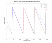
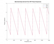
Here's 4096 taps @ 48kHz minimum-phase FIR filter via rePhase. Single EQ as shown, Butterworth 3rd order high pass at 30 Hz. That's it for filters.
Impulse center at sample 1, and predicted match.
Impulse center at 2028 taps, and predicted match.
Different frequency resolutions equal different predicted matches, no ?
Here's the minimum-phase FIR filter generated by rePhase.
If the convolution steps you laid out give a 4k tap linear-phase version that can equal the frequency resolution of the attached 4k tap min-phase version, that will be a heck of a learning revelation for me..........
I can't readily do the steps. If you can/will, many thx (change .zip extension to .wav)
Attachments
Hi Oabeieo, i can say from a bit of experience trying, that 1024@96k can't do much in the 70-100Hz range.So that’s why when I have low taps (1024@96k) and I’m doing a linearizarion adound 70-100hz , I have to do centering at around 9-10ms for it to work right….
I just learned something thanks that really cool…. Yeah that would be a little forward of the peak I would guess.
First, because 1024@96k has the same effective frequency resolution as 512 taps@ 48k. Which isn't much....
And second, because the 600 or so taps I was talking about using for a 24dB LR at 100Hz, works only because the LR xover itself is a rather smooth animal in terms of changing freq response. Iow, relatively higher Q Eq's , or xover orders, etc, will not work with that few taps.
It all depends upon what approximation techniques RePhase is using. I've never used RePhase, so I can't help with that.Different frequency resolutions equal different predicted matches, no ?
I don't know those techniques either, but I don't think they should matter much.....at least not in comparison to the difference in frequency resolution when one filter has twice the effective taps as the other. (impulse at start vs at center)It all depends upon what approximation techniques RePhase is using. I've never used RePhase, so I can't help with that.
Let's just set rePhase completely aside.
If you can take the convolution steps on the minimum-phase FIR file i attached and provide your linear-phase version,
then I will run a transfer function on the two versions.
No better proof positive than that, i think.
It’s the same as 2048 at 48k (not 512)Hi Oabeieo, i can say from a bit of experience trying, that 1024@96k can't do much in the 70-100Hz range.
First, because 1024@96k has the same effective frequency resolution as 512 taps@ 48k. Which isn't much....
And second, because the 600 or so taps I was talking about using for a 24dB LR at 100Hz, works only because the LR xover itself is a rather smooth animal in terms of changing freq response. Iow, relatively higher Q Eq's , or xover orders, etc, will not work with that few taps.
But yeah , when it’s all you got , centering I the 9ms area adds a whole bunch more phase control….
But to your previous point, it won’t let me go past I think 10.66ms iirc , idk why, maybe fir is simply shorter then 10.33ms is the max , where exact centering takes me to 5.33ms, so yeah a little past the center of ir seems to give better phase control…. At the lower frequencies…. And thinking what you said about the first half being iir, it made sense a little
I thought it had something to do with the wavelength of the frequencies, but what your saying makes me think the length of the fir….. so thanks.
- Home
- Loudspeakers
- Multi-Way
- Why not IIR filters + a global phase linearization by FIR