The concept of group delay and "group delay distortion" IIRC originally came out of the development of analog telephone lines and the efforts to improve intelligibility of call information. Here is something related to that (sorry it is a bit simplistic, I cannot find a more scientific version related to analog telephone transmission):
http://www.telecomworld101.com/Intro2dcRev2/page83.html
They refer to GD as "envelope distortion". Note it is not the same as the propagation delay.
I think the problem with the vagueness in the definition is that many people talk about group delay when working on a circuit or other system that has no propagation delay, like an filter or whatever, where they are just injecting the signal to the filter's input and then measuring the group delay at the filter's output. The fact that it the group delay is WRT to the signal envelope has been largely forgotten.
Maybe reading this will convince you of my point of view, gberchin and others?
https://audioxpress.com/article/voi...oup-delay-and-impulse-response-a-quick-primer
From the text just below the large equation defining group delay:
If anyone would like to PM that article to me I would be much obliged. I do not have JAES access.
https://audioxpress.com/article/voi...oup-delay-and-impulse-response-a-quick-primer
From the text just below the large equation defining group delay:
The source for that is: Vanderkooy and S. P. Lipshitz, “Uses and Abuses of the Energy-Time Curve,” Journal of the Audio Engineering Society, Vol. 38, No. 11, November 1990, pp. 819-836.Group delay, by definition, represents the system delay as a function of frequency, with any processing, propagation, or other “all-pass” delay (sometimes referred to as “excess phase”) removed from the calculation
If anyone would like to PM that article to me I would be much obliged. I do not have JAES access.
Again, I'm OK with your definition, as long as your assumptions (various time delays removed) are made explicit. Otherwise I default to the mathematical definition.Maybe reading this will convince you of my point of view, gberchin and others?
Again, I'm OK with your definition, as long as your assumptions (various time delays removed) are made explicit. Otherwise I default to the mathematical definition.
The problem is that there is more to the "definition" than just the mathematical expression on how to calculate the value...
For anybody who might be interested: I have created a short document describing how to modify the Matched-Delay Subtractive Crossover to exhibit 24 dB / octave highpass slope. If you don't want to wade through the math, then just skip to page 3 to find instructions on how to implement.Just a hint of foreshadowing: a variant with 24 dB / octave highpass slope is under development.
If anybody finds an error, please let me know.
Attachments
Thanks for sharing your approach ! Have not yet read it carefully, but looks interesting. I have realized 4th order HP subrstractive crossover using classical approach, i.e. using single delay line and cascaded LP filters. However, such approach requires numerical optimisation of both LP filters and the delay value. Here is example of crossover for 15" Tannoy Gold loudspeakers (green line corresponds to summed FR)For anybody who might be interested: I have created a short document describing how to modify the Matched-Delay Subtractive Crossover to exhibit 24 dB / octave highpass slope. If you don't want to wade through the math, then just skip to page 3 to find instructions on how to implement.
If anybody finds an error, please let me know.
I maybe missing something but why is it that we've to delay-subtract each time and then cascade them and delay-subtract again? Is there any reason why we can't have the delay-subtractor around a 4th order LPF directly ?For anybody who might be interested: I have created a short document describing how to modify the Matched-Delay Subtractive Crossover to exhibit 24 dB / octave highpass slope. If you don't want to wade through the math, then just skip to page 3 to find instructions on how to implement.
If anybody finds an error, please let me know.
BTW, I've added Bessel filtering (upto 4th order) to my processing unit after having read your other paper!
Last edited:
For anybody who might be interested: I have created a short document describing how to modify the Matched-Delay Subtractive Crossover to exhibit 24 dB / octave highpass slope. If you don't want to wade through the math, then just skip to page 3 to find instructions on how to implement.
If anybody finds an error, please let me know.
Perhaps I misunderstand a cursory first glance (just got back from hiking, an excellent Szechuan supper, and a couple of drinks), but wouldn't h4'(t) have rolloff characteristics similar to g^2 since the h4'(t) summing node subtracts the delays from the top path from the delays in the bottom path, leaving two LPF sections in series, each convolving their input with g? It also looks as if h4'(t) is out of phase with the input and/or highpass since the passband goes through three inversions. Moreover, the structure could be generalised to higher orders, with hN'(t) in phase with the input/HPF for N/2 odd since the number of inversions will be even. Is this correct? If so, then the various section lowpass frequencies could be different to produce a more gradual transition at the crossover point while still keeping the asymptotic steep rolloff for the highpass.
Do please tell me if I'm off the beam, thanks.
Perhaps I don't understand the question. You can use any order Bessel LPF that you want, and the complementary HPF will still only have a 12 dB / octave slope. That's the problem -- some people expressed a desire for a steeper HPF slope.I maybe missing something but why is it that we've to delay-subtract each time and then cascade them and delay-subtract again? Is there any reason why we can't have the delay-subtractor around a 4th order LPF directly ?
One of the unique properties of the Gaussian shape is that the convolution of two Gaussians produces another Gaussian. So "g^2" still has a Gaussian shape.Perhaps I misunderstand a cursory first glance ..., but wouldn't h4'(t) have rolloff characteristics similar to g^2
Work the math: we are convolving "1 - Gaussian" with "1 - Gaussian", producing "1 - 2Gaussian + Gaussian^2". That results in the highpass output. Then for the complementary lowpass output, we are computing "1 - (1 - 2Gaussian + Gaussian^2)", producing "2Gaussian - Gaussian^2".It also looks as if h4'(t) is out of phase with the input and/or highpass since the passband goes through three inversions.
It may be possible, but remember the stated objective in the original paper: the shortest impulse response possible for a given bandwidth, with no overshoot or ringing. My objective in this 24 dB / octave highpass variant was to compromise the impulse response as little as possible, and the resulting impulse does, in fact, overshoot and ring slightly. Other approaches are possible, of course, but each one will compromise the impulse response and the frequency response in different ways. As with all engineering problems, it is up to the engineer to decide which compromises are acceptable and which are not.Moreover, the structure could be generalised to higher orders, with hN'(t) in phase with the input/HPF for N/2 odd since the number of inversions will be even. Is this correct? If so, then the various section lowpass frequencies could be different to produce a more gradual transition at the crossover point while still keeping the asymptotic steep rolloff for the highpass.
For anybody who might be interested: I have created a short document describing how to modify the Matched-Delay Subtractive Crossover to exhibit 24 dB / octave highpass slope. If you don't want to wade through the math, then just skip to page 3 to find instructions on how to implement.
If anybody finds an error, please let me know.
I read your document more carefully and I have some comments/considerations.
To analyze your proposed scheme, I used complex transfer functions, since it is more conveniet for analysis.
While relative phase of substractive stage 1 and stage 2 is important in your proposed scheme, let us say that HP and LP crossovers at stage 1 are connected in-phase, while substractive stage 2 we consider both for in-phase and out-of-phase connection.
Linear phase (=constant delay) condition for substractive stage 1 is
Hhp1(s) + Hlp(s) = exp(-tau1*s)
So, to satisfy this linear phase condition, Hhp1 output must be equal to
Hhp1(s)=exp(-tau1*s) - Hlp(s) .
Then, linear phase condition for the second stage is
Ih-phase case
Hlp2(s)+Hhp2(s)=exp(-tau2*s)*Hhp1(s)
Out-of-phase case
-Hlp2(s)+Hhp2(s)=exp(-tau2*s)*Hhp1(s)
So, let's find output Hhp2 of substractive stage 2 for stage 1 and 2 connected in phase and out of phase.
1. Stage 1 and Stage 2 In phase.
Hhp2(s)=exp(-tau2*s)*Hhp1(s) - Hlp2(s)
Hhp2(s)=exp(-tau2*s)*[exp(-tau1*s) - Hlp(s)] - [exp(-tau1*s) - Hlp(s) ] *Hlp(s)
= exp(-(tau1+tau2)*s) - exp(-tau2*s)*Hlp(s) - exp(-tau1*s)*Hlp(s) + Hlp(s)*Hlp(s) =
= Hlp(s)Hlp(s) - Hlp[exp(-tau1*s)+ exp(-tau2*s)] + exp(-(tau1+tau2)*s) =
For tau1=tau2=tau
Hhp2(s) = Hlp(s)*Hlp(s) - 2*Hlp*exp(-tau*s) + exp(-(2*tau)*s)
So, if stages 1 and 2 are connected in phase we get 4th order LP crossover.
2. Stage 1 and Stage 2 out-of-phase
Hhp2(s)=exp(-tau2*s)*Hhp1(s) + Hlp2(s)
Hhp2(s)=exp(-tau2*s)*[exp(-tau1*s) - Hlp(s)] + [exp(-tau1*s) - Hlp(s) ] *Hlp(s) =
exp(-(tau1+tau2)*s) - exp(-tau2*s)*Hlp(s) + exp(-tau1*s)*Hlp(s) - Hlp(s)*Hlp(s) =
exp(-(tau1+tau2)s) + Hlp[exp(-tau1*s) - exp(-tau2*s)] - Hlp(s)*Hlp(s)
For tau1=tau2=tau
Hhp2(s) = exp(-2*tau*s) + Hlp*[exp(-tau*s) - exp(-tau*s)] - Hlp(s)*Hlp(s) = exp(-2*tau*s) - Hlp(s)*Hlp(s)
So, if stages 1 and 2 are connected out of phase, we get 4th order HP filter. (Note, that the same result we can get just by substracting output of two serially in-phase connected Hlp from input signal delayed by 2*tau (actually, frequency responses in my graph above demonstrates this case)).
Yes.The fact that it the group delay is WRT to the signal envelope has been largely forgotten.
Forgotten to the point that group delay becomes attributed to all kinds of erroneous associations, sometimes even as a substitute for fixed delay.
And when audibility studies are based on group delay, aren't they really studying audibility of envelope distortion? Seems so to me.
A valid study of envelope distortion at low frequencies, say 20-300Hz, is what I'd like to see.
Hhp2(s) = exp(-2*tau*s) + Hlp*[exp(-tau*s) - exp(-tau*s)] - Hlp(s)*Hlp(s) = exp(-2*tau*s) - Hlp(s)*Hlp(s)
So, if stages 1 and 2 are connected out of phase, we get 4th order HP filter.
Try it with Hlp(s) a Gaussian. The resulting HPF will still only have 12 dB / octave slope.
Yes, understood (picture). Thanks.You can use any order Bessel LPF that you want, and the complementary HPF will still only have a 12 dB / octave slope. That's the problem...
Attachments
Try it with Hlp(s) a Gaussian. The resulting HPF will still only have 12 dB / octave slope.
As far as I remember, it was demonstrated long time ago by Ng and Rothenberg in IEEE paper. Maybe I'm missing some point and I need to describe the mathematics of your method in more detail, however, primary analysis using complex transfer functions shows that the result should be similar in both cases (i.e. using two serially connected substractive stages vs single substractive stage with two serially connected LP filters).
If you can show that "1 - (GaussianLPF * GaussianLPF)" (with appropriate delays) has a 4th-order highpass slope, then I would be very interested in this. It would simplify the solution by a considerable amount. I remain skeptical, however.As far as I remember, it was demonstrated long time ago by Ng and Rothenberg in IEEE paper. Maybe I'm missing some point and I need to describe the mathematics of your method in more detail, however, primary analysis using complex transfer functions shows that the result should be similar in both cases (i.e. using two serially connected substractive stages vs single substractive stage with two serially connected LP filters).
Obviously, that it can't be demonstrated that two serially connected Gaussian filters have 24dB/oct slope. Even simple cosideration of expressionIf you can show that "1 - (GaussianLPF * GaussianLPF)" (with appropriate delays) has a 4th-order highpass slope, then I would be very interested in this. It would simplify the solution by a considerable amount. I remain skeptical, however.
1-exp(-a*s^2)*exp(-a*s^2)=1-exp(-2*a*s^2) shows, that two serially connected gaussian filters still remain second order crossover. I missing the point, why two serially connected substractive stages gives 4th order Gaussian crossover as supposed by your design using convolution.
It doesn't. That's not what I created. I started with (1 - GaussianLPF), which has a 2nd-order highpass slope, and convolved it with itself, resulting in a 4th-order highpass slope. Neither of those highpass filters has a Gaussian shape. The lowpass complement of the convolution has slope approximately equal to the slope of the original GaussianLPF. Not exactly equal, just approximately equal.I missing the point, why two serially connected substractive stages gives 4th order Gaussian crossover as supposed by your design using convolution.
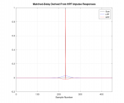
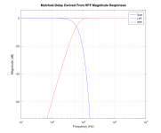
I've attached some graphics showing an example. For this I used a true Gaussian LPF and adjusted the width empirically to achieve an ultimate crossover frequency of 600 Hz. The resulting impulse and step responses are as shown. If you look at the highpass frequency response between 100 Hz and 200 Hz, you'll see that it changes by approximately 24 dB. Meanwhile, the lowpass response still rolls-off very steeply.
Attachments
That looks quite nice to me, for when I could use 24 dB/oct high pass. (I really like the low-pass steepness!)If you look at the highpass frequency response between 100 Hz and 200 Hz, you'll see that it changes by approximately 24 dB. Meanwhile, the lowpass response still rolls-off very steeply.
I can't follow the paper you posted, but I see delays are used.
If xover is at 100Hz, what would the totally fixed delay be?
@gberchin , those look like excellent lin-phase target functions for an XO, thanks for posting this (and the corresponding paper). Being lin-phase filters, it will be also easy to extend that for more XO points. Time-domain behavior is really compact with minimal ringing.
For loudspeaker XO we will have to factor in the drivers' transfer functions to obtain the actual electrical filters but with modern DRC packages like Acourate it is not overly complicated to arrive at the proper FIR filter kernels. In some cases we might get away with relatively simple IIR post-filters to linearize drivers in magnitude and phase over the required range and thus we can use the implementation of the targets directly as is.
For loudspeaker XO we will have to factor in the drivers' transfer functions to obtain the actual electrical filters but with modern DRC packages like Acourate it is not overly complicated to arrive at the proper FIR filter kernels. In some cases we might get away with relatively simple IIR post-filters to linearize drivers in magnitude and phase over the required range and thus we can use the implementation of the targets directly as is.
- Home
- Loudspeakers
- Multi-Way
- Why not IIR filters + a global phase linearization by FIR


