[HV PNP is easier to find with constant Beta, HV P channel is getting rare now, FQP1P50 I think is obsoleted]
I have been using FQP3P50. It makes a fine p-chan follower.
Can always just put 5 matched 12HL7 in parallel to get a 50 Watt "triode" tube with 105,000 gm (no driver needed!) Maybe 20 of them for a P-P 100 Watt "Triode" Amp.
As soon as I finish with ongoing 2 projects, I will start with 22x 6P15P project (10 in parallel per channel) 😀
Price of 6P15P is going to go up!!
-------------------
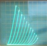
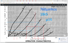
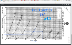
1) 6HJ5 in triode (typical T curves for most Sweep tubes)
2) 6HJ5 in Schade (gain approx. 4)
-------------------
1) 6HJ5 in triode (typical T curves for most Sweep tubes)
2) 6HJ5 in Schade (gain approx. 4)
Attachments

Last edited:
Price of 6P15P is going to go up!!
I don't think so... Still, 48W for filament, almost like 813... Something else is needed... May be 3x GU-50? 🙂
Russian tubes rock
The amp sounds absolutely beautiful ! It would be good to see more of your amp testing posted on youtube .
What is that piece of organ called , and by whom ?
I'm loving this thread , and am taking notice of unknown tubes mentioned , I'm a big fan of the Russian tubes and caps , especially at decent prices .
Thanks for pointing out Vacuum Tubes - Audio Tubes - ESRC Vacuum Tubes - Electron Tubes Smoking-amp ! 🙂
Like that your amp will not smoke for shure 😉"Cheating" 😀
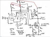
the "Cheating" "Triode" Buffer Amp
still could use a DC bias servo loop, to keep the output at 0V (at least a bias adjust pot on V2 grid 1)
The BJT never conducts.
And why not two mosfets ?
There are other not so expensive triodes like the 6080 🙂, no need to cheat

Mona
Attachments
Woops! U R so right Mona!
Guess I wrote that down a little quickly.
The bipolar, at Q1, was used due to its constant current gain Beta and near constant 0.6V drop, not introducing any significant I or V distortion into the driving triode output. (so preservation of the "triode" characteristic). However, a Mosfet at Q1 would reduce the loading on V1 for lower tube distortion. (but this IS supposed to sound like a tube!)
The Mosfet at Q2 is only providing a complementary current source to Q1, so not as important V distortion wise. But the amp could be worked out with Mosfets or Bipolars in either position, due to the N feedback to the V1 screen.
This is emulating the near "perfect" 1E7G (or 1F5G) "triode" curves. 6080 and other regulator tubes are not so perfect. (too much roll-over in the plate curves) I'm still trying to figure out something comparable to "Crazy Drive" for fixing up triodes too, but have only found complicated, pointless (like Schade around a cascode) (or unlikely) schemes so far.
---------------------------------
"Thanks for pointing out Vacuum Tubes - Audio Tubes - ESRC Vacuum Tubes - Electron Tubes Smoking-amp ! "
Check also VacuumTubes.net when looking. Another favorite site.
---
Last edited:
"Still, 48W for filament, almost like 813... Something else is needed..."
The 12HL7 or 6P15P tubes are about as efficient as the big TV sweep tubes as far as cathode current versus heater current. Maybe you don't need 22 tubes.
Is this going to be class A or class AB for ?? Watts output?
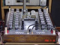
The big problem, I think, is the number of sockets, and the individual tube biasing or tube matching. Still, 22 tubes would look impressive. Eh, maybe use 50!! Like this one (OTL):
The 12HL7 or 6P15P tubes are about as efficient as the big TV sweep tubes as far as cathode current versus heater current. Maybe you don't need 22 tubes.
Is this going to be class A or class AB for ?? Watts output?
The big problem, I think, is the number of sockets, and the individual tube biasing or tube matching. Still, 22 tubes would look impressive. Eh, maybe use 50!! Like this one (OTL):
Attachments
4P1L: 1.5W filament for 11W anode,
6P15P: 5W for 12W anode,
GU-50: 1.4W for 40W anode
3xGU50 is the winner.
6P15P: 5W for 12W anode,
GU-50: 1.4W for 40W anode
3xGU50 is the winner.
The amp sounds absolutely beautiful ! It would be good to see more of your amp testing posted on youtube .
What is that piece of organ called , and by whom ?
Adagio dAlbinoni, Gari Karr. Amati contrabass, 1610. It is 2'stage pentode amp, with local feedback around output tubs, class A2. That's why linearity and output impedance better than triode, and power is higher than in case of wasteful arrogant triode connection. I.e. high-tech usage of vintage tubes. SMPS for filaments
Last edited:
GU-50: 1.4W for 40W anode
O.K. sovjets were good with propaganda, but I didn't know they were soo good ;-)
GU-50 more like 10W heater power (12.6v * 0.8a) ... ?
still winner !
Ouch... My bad, 10W! 😀
Here is the previous amp prototype, Gubernator - 71
https://www.youtube.com/watch?v=iCUFJF_j108#action=share
Here is the previous amp prototype, Gubernator - 71
https://www.youtube.com/watch?v=iCUFJF_j108#action=share
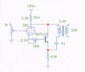
I'm going to build a triodelington - just for fun. This Bjt is the best I could find: http://www.mouser.com/ds/2/149/BUT11AF-102541.pdf
I ordered a few and tested them. Very consistent beta of about 23. Mu of around 10, and linear at low current for the valve would be nice. I'll actually make it as a headphone amp if it works well. Plan is a very simple, resistor loaded parafeed, with a small toroid output, and primary returned to emitter resistor. Was planning on using 3A5, but triode connected pentode might be even more fun.
Now that we've sorta highjacked this thread (but in good fun), here's what I was thinking. Remember, it's for fun, and yes, I know it's completely unnecessary. Now, if I could combine this with crazy drive, without too much gain, and at 1-2ma for the tube, that would be really fun.
Blastered child of Oldeurope and Smoking amp - a new level of weird and wonderful!
Sheldon
Attachments
Last edited:
Not sure how you would get Crazy Drive in there. It's a good V to I stage.
I came up with this the other day for a Schaded Crazy Drive (turning it into a "triode"). I think Anatoliy had something similar once for a PSRR fixup for g1 driven Schade.
G2 drive or Crazy Drive does not leave as much loop gain available for Schade N Fdbk as normal G1 drive. (which would not lower Zout so much) So this uses a P channel Mosfet driver stage to greatly improve the Fdbk. (and the PSRR too for the Schade) Should end up with a rock solid low Zout, and a Schade emulation of a triode with remarkable linearity. (the Crazy Drive being very linear for V to I to start with, and then the high loop gain Schading with the Mosfet) The P Mosfet also solves the high voltage drive swing issue for Crazy Drive or g2 drive.
(the Mosfet needs a gate stopper resistor yet)
Attachments
Last edited:
Yep, that's it. Excellent idea.
If only we had a P tube now. But the Mosfet is easy to hide under the chassis at least.
If only we had a P tube now. But the Mosfet is easy to hide under the chassis at least.
Yep, that's it. Excellent idea.
If only we had a P tube now. But the Mosfet is easy to hide under the chassis at least.
It is what I use in my hybrids now, a P-output tube, directly coupled to N-driver tube. ;-)
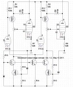
Getting back to the power triode subject more directly, one should mention this scheme posted by Goldenbeer recently.
Over Unity Positive feedback from the output OT to the driver stage bootstrapped loads. It apparently nulls out 3rd harmonic distortion of the 6080 (or any regulator type triode, with plate curve rollover) by sloping the 6SN7 driver loadlines with an effective negative resistance. (the loadline slopes upwards at higher plate V, the opposite of the norm) This allows one to put expansive 3rd harmonic into the 6SN7 driver output, to null out the compressive 3rd harmonic from the output tubes. See below. (R12 and R13 look like Schade feedbacks, but they are crossed to the opposite plates to get positive Fdbk)
Global N Fdbk keeps the whole thing under control. Although it would be safer to put some "local" N Fdbks around the P Fdbks, so the OT bandwidth does not become a stability issue at HF. (The N Fdbks need to remain effective at HF, to prevent oscillation from the over unity positive feedbacks. Global N Fdbk might not make it.)
This general theme can be used in other ways. I have been thinking of using P Fdbk driver bootstrapping (somewhere below unity gain, not over unity gain) to get sufficient drive for g2 or Crazy drive. Then some "local" (no OT in loop) N Fdbks around that to keep it stable. (OT UL taps used for positive bootstrap sources to the driver loads, and also used for N Fdbks to the driver grids or cathodes. Phased correctly. More gain in the N loops.) (one could TRY over unity gain in the P Fdbk loops to eliminate any 3rd harmonic, as long as it all stays stable)
The scheme however does not address higher harmonics (than 3rd). Which are likely to be non negligible if starting from a poor quality triode characteristic. But then one could try the resistive tail trick on a differential driver stage, adjusted to null 5th or 7th harmonic of the whole amp. ( I do see a 560 Ohm R14 in the Goldenbeer amp schematic driver stage below.)
Attachments
Last edited:
- Status
- Not open for further replies.
- Home
- Amplifiers
- Tubes / Valves
- Why is a (power) triode so expensive?