Popilin, who has provided some thought-provoking analyses, has pointed out that a simple calculation of emission without regard to fields can be misleading.
Quite apart from the fact that electron emission from the cathode is just not relevant to the evaporation of Ba from the cathode, as I have pointed out, his guess (It is a guess, he hasn't actually done any calcs, nor does he show understanding of all the terms (Va ??) in the equations he quotes) that electric fields need to be taken into account has no sunstantive basis in fact. The fact is, as any textbook on thermionic emssion will confirm, schottky effect has no applicability to pure metal cathodes, and makes only a few percent difference with oxide cathodes.
Keit
I introduced the grid contamination issue on post#17, on your words; I already gave you the solution… 😉
Another advantage is that gold (coated) grids are less prone to contamination in valves with oxide cathodes.
It was not until post # 25 that you realize about the issue
Grids tend to get contaminated with oxide material vaporised off the cathode. This makes the grid emit electrons and thus make the grid go positive - which can be disasterous. The oxide material does not adhere well to gold, so any vaporised cathode material is more likely to go somewhere else where it does less harm.
Later, already with the answer, you began to mistreat other members, but so far, it has been proven that you have no idea about basic physics of a valve, e.g. electrodynamics, thermionic emission, Schottky effect...even you confused primary emission with secondary emission; and now you intend to teach us about everything, repeating like a parrot that books say.
My results are not a guess, but experimental results from measurement of the work function for an oxide coated cathode.
As it seems that you have not understood the issue, I will repeat the procedure.
Richardson-Dushman equation
Jo = Ao T² exp ( - e φ / k T )
It is valid with no applied external electric field.
Applying an external electric field, at saturation, Richardson-Dushman equation takes the form
Js = Jo exp{e √[e E / (4 π ε0)] /(k T)},…..(*)
As it is very difficult to measure E at the cathode surface, i.e. you need a test charge and measure the force exerted by the field, you can measure the voltage applied between anode and cathode, then applying an accelerating potential, Va, for a high value enough, current density reaches its saturation value, Js
Js = Jo exp [(α √ Va ) / (k T)],…..(**)
Then, α can be obtained from the straight line
Ln (Js) = [α / (k T)] √ Va + Ln (Jo)
From experimental results
α ≈ 7.74 x 10⁻³
From (*) and (**) we find
E = 4 π ε0 α² Va / e
Then, for Va = 60 V
E ≈ 2.5 MV/m
My Tarzan-English should make things hard for you, but you don't need a cryptologist. 😀
BTW, I have no seen any calculation from you, except perhaps on post#6
Do the math, folks.
A typical RF receiving tube has grid wire of the order 30 um radius, wound on a mandrel 5 mm diameter, around 30 turns. That's a wire 470 mm long having a surface area 89 x 10^-6 square meters.
A typical gold plating thickness is 10 um. So the volume on the wire is 89 x 10^-10 cubic meters. That will weigh 17 milligrams (density of gold 19300 kg/m^3) and at the current price of US$37/gram (source: Gold Price per Gram), be worth 63 cents.
On post#31, with Boltzmann constant ten orders of magnitude greater
The work function of gold 5.1 eV is the same as for nickel, and not much better than that of molybdenum, 4.9 eV. Using T = 1050 K and kB = 8.617x10^05, we see that the exponent varies from about -54 to -56, which changes the emission by one order of magnitude.
Nothing more, mate, only
Blah blah blah blah.........
Last edited:
Fated Lambs
OK we will lead the lambs to the slaughter. I am in Ann Arbor MI all week for a confrence. We can exchange PM's to discuss the run in conditions; volts, MA and days or hours for the long duration pair.
DT
OK we will lead the lambs to the slaughter. I am in Ann Arbor MI all week for a confrence. We can exchange PM's to discuss the run in conditions; volts, MA and days or hours for the long duration pair.
DT
Just missing one another- I'll be there in a couple more weeks. Anyway, drop me an email and we can figure things out. And don't forget to go to Zingerman's.
Ok, still kicking about whether chemical conversion of BaO to Ba-Au alloy liberating O2 might be feasible at the gold surface. Looking at enthalpy, the reaction seems short of about 3.5eV or so to proceed. Presumably that might be the activation energy for the reaction (?)
So, how do I work out whether a temperature of say 650K might be sufficient to provide 3.5eV often enough to be interesting ? Looking at the Arrhenius equation, I seem to be short of a constant 'A' in units of s-1
Any ideas ?
So, how do I work out whether a temperature of say 650K might be sufficient to provide 3.5eV often enough to be interesting ? Looking at the Arrhenius equation, I seem to be short of a constant 'A' in units of s-1
Any ideas ?
OOops, 3.5eV is probably significantly overstating activation energy, as forgot the formation enthalpy of Au-Ba is exotherthermic. But my question about how to relate activation energy to reaction rate in this case remains......?
I believe the 6P1P-EV also has gold grid wires.
I'll check and see if I can tell without busting them open.
I'll check and see if I can tell without busting them open.
FYI, it's quite probable that many crummy TV tubes had gold grids, such as vertical output types. I'd suggest a NIB/NOS sample and a well used, faded-getter version.
I don't have such a pair in my collection, but I'm betting some of you are just dripping with possible examples. 🙂
Tim
I don't have such a pair in my collection, but I'm betting some of you are just dripping with possible examples. 🙂
Tim
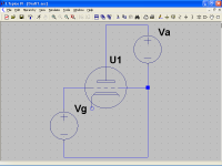
I have more-or-less completed the 6AL5 model:

V1 is for DC sweep.
Remains to put an exponential cutoff on the power term, to aid convergence (SGN is discontinuous), and if anyone wants to play with dynamic terms (capacitance is obvious, lead inductance somewhat less so, space charge who knows), that's yet to be seen as well.
I have a suspicion that the remaining leakage I've observed is actually coming from the heater; the reverse bias testing was done with heater from -V to GND, plate adjustable -V to 0V, cathode grounded. This contributes to IS slightly, and mostly to R1.
Tim
It's a fair cop, but society is to blame.......... need to be sure of the types.I don't have such a pair in my collection, but I'm betting some of you are just dripping with possible examples. 🙂
I was thinking on an experiment, easier and cheaper.
However I only can offer to make the calculations. 😀
However I only can offer to make the calculations. 😀
Third world style experiment
Some small RF triodes have more than one grid connection, in the case that these connections are separated for both grid rods, the grid can be heated with a PSU and it can be like a cathode.
Grid material is not so important in order to compare a new one with an old contaminated grid, let's suppose a molybdenum grid.
e φ = 4.15 eV,..... Ao = 55 A/(cm² ºK²)
Then, at 1000 ºK
Jo(Mo) ≈ 6.7 x 10⁻¹⁴ A/cm²
This means, for a typical receiving valve with grid surface of about 1 cm²
io(Mo) ≈ 6.7 x 10⁻¹⁴ A
This should be almost immeasurable for a new clean grid, but for an old contaminated grid, e.g. with Barium
e φ = 2.52 eV, ..... Ao = 0.06 A/(cm² ºK²)
Then, at 1000 ºK
Jo(Ba) ≈ 1.19 x 10⁻⁸ A/cm²
Supposing that almost all grid surface is contaminated
io(Ba) ≈ 1 x 10⁻⁸ A
This is easily measurable with a picoammeter.
Unfortunately we cannot follow the standard procedure as on post#138, because with a retarding potential, current will be too low, then forget to measure grid temperature and work function, but not all is lost, we can measure emission.
Again, from Richardson-Dushman equation
Jo = Ao T² exp ( - e φ / k T )
Applying an accelerating potential, Va, for a high value enough, current density reaches its saturation value, Js
Js = Jo exp [(α √ Va ) / ( k T )]
Then, you can obtain Jo from the straight line
Ln (Js) = [α / ( k T )] √ Va + Ln (Jo)
Seems to me a good idea to preheat the valve, with its heater at maximum allowed for some hours in order to eliminate as much gas as possible; cathode poisoning does not care anymore, and the other benefit is to contaminate the grid a bit more.
The most difficult is to maintain the grid hot enough to measure some current and cold enough to not destroy it.
Needless to say that temperature must be about the same on both cases, so supposing "identical" grids it must be ensured about the same "grid power" from the grid PSU.
I never did the experiment this way, but I guess that with a new uncontaminated grid, saturation current should be too low to measure; if not, comparing with measurement of an old contaminated one should be orders of magnitude lower.
If both measurements are comparable, we will need to think on another explanation.
Suggestions welcome. 😀
Attachments
Last edited:
Or... we can just look directly at the surface of grids from new, slightly used, and well-used tubes. That avoids confounders like gas.
Since I have the equipment to do this, which guys who wrote textbooks 60 years ago didn't, it seems worth a shot.😀
Since I have the equipment to do this, which guys who wrote textbooks 60 years ago didn't, it seems worth a shot.😀
Some small RF triodes have more than one grid connection, in the case that these connections are separated for both grid rods, the grid can be heated with a PSU and it can be like a cathode.
An idea that is totally impractical.
Impractical because because the resistance across the grid is milliohms at most, and much less than the pin-to-socket resistance.
But you can measure grid emission in a much eaier way: Just set up the tube under test in a standard circuit, cathode voltage bias, grid earthed via a micoammeter. Any grid emission that occurs must flow in the grid leak, along with the small current due to contact potential.
As the tube ages, the current in the grid leak changes from a slight negative value (due to contact potential) to a larger positive value (due to grid emission). One can extract further information by manipulating heater voltage (which changes contact potential in a predictable way) and by manipulating anode voltage (or screed grid voltage in a tetrode or pentode), and manipulating the bias voltage, which opposes contact potential but has only a tiny effect on grid emission.
In a tube with a gold plated grid, the change in grid leak current in the postive direction occurs much more slowly that with a nickel grid.
Of course, those of us who were employed in electronics in the Years Before Transistor already know all this.
Many books on tube testing (proper testing, not the simplified testing done in radio shops) cover the standard way to measure grid emission. A good example is in The Radiotron Designer's Handbook, Section 3.3 (iv) (c) Grid Primary Emission, page 102 (4th ed 1953).
Last edited:
An idea that is totally impractical.
Impractical because because the resistance across the grid is milliohms at most, and much less than the pin-to-socket resistance.
Reference? Calculation? 🙄
But you can measure grid emission in a much eaier way: Just set up the tube under test in a standard circuit, cathode voltage bias, grid earthed via a micoammeter. Any grid emission that occurs must flow in the grid leak, along with the small current due to contact potential.
As the tube ages, the current in the grid leak changes from a slight negative value (due to contact potential) to a larger positive value (due to grid emission). One can extract further information by manipulating heater voltage (which changes contact potential in a predictable way) and by manipulating anode voltage (or screed grid voltage in a tetrode or pentode), and manipulating the bias voltage, which opposes contact potential but has only a tiny effect on grid emission.
In a tube with a gold plated grid, the change in grid leak current in the postive direction occurs much more slowly that with a nickel grid.
Of course, those of us who were employed in electronics in the Years Before Transistor already know all this.
Many books on tube testing (proper testing, not the simplified testing done in radio shops) cover the standard way to measure grid emission. A good example is in The Radiotron Designer's Handbook, Section 3.3 (iv) (c) Grid Primary Emission, page 102 (4th ed 1953).
Easier... 😛😀
Reference? Calculation?
Here is data for the small framegrid WE 417A VHF triode, which is probably the most favourable for your proposed method, compared to other dual grid-pin tubes:-
Grid wire diameter............0.0074 mm
Grid pitch.......................0.065 mm
Grid half turn length.........~5 mm
Cathode length...............~8 mm
Most grids in receiving tubes are made of nickel.
The resistivity p of nickel @ 300 K is 6.99 x 10⁻⁸ ohm.meters. At 500 K it is about 17.9 x 10⁻⁸ ohm.meters (Ref: Isotek website - pure nickel datasheet)
For each grid wire half-turn, the resistance at 500 K is:-
R = p L / A ohms (L = length; A = cross section area)
R = 17.9x10^-8 x 0.005 / [pi (7.4x10⁻⁶ / 2)^2]
R = 21 ohms.
Number of grid half turns = 2 x Lcath / Pitch
Number of grid half turns = 2 x 8 / 0.065
Number of grid half turns = 246.
Therefore, total grid resistance = 21/246 = 0.085 ohms.
Similarly, the cold grid resistance will be about 0.033 ohms.
Pin-socket resistance of a noval tube socket is about 50 milliohms at best according to my McMurdo catalogue, so to use both grid pins on a tube designed for grounded grid operation, you have to energise 0.085 ohms through an extra 0.100 ohms.
All this assumes that all the grid turns heat equally. That is unlikely to be the case, so electrically heating the grid is not practical.
If the grid is gold plated, the question arises as to what the plating/cladding thckness is. However, the practicallities of plating means that gold thickness will account for a large fraction of the grid wire x-section area. The resistivity of gold is only about 32% of that of nickel, making electrically heating gold grids even more impractical. In a large power tube, the gold may account for only a small part of the x-section area, but then you won't have 2 grid pins.
Just measure grid primary emission by the standard method decribed in textbooks: Measure the grid current while manipulating bias etc to enable subtacting out current due to contact potential.
Now, Popilin, how about you doing some actual calculations, setting out specifically what each of the terms mean in those equations you keep repeating, putting numbers on them. Can you? Do you dare?
Here's something you should attempt: The amount of energy required to heat the grid to an appropriate temperature (based on radiation and conduction paths) can be calculated - it's set out in great detail in Heat Transfer in Receiving Tubes, O H Schade, RCA 1962. Then you can calculate the required current. You'll find that the tube socket will not take that amount of current.
Last edited:
All good stuff as ever, popilin. I agree with you posts as to effect of external field on emission, BTW; I reached a similar conclusion a whilst back but probably didn't explain it so clearly.........let's suppose a molybdenum grid...... e φ = 4.15 eV,.....
e.g. with Barium e φ = 2.52 eV, .....
Interesting idea, your experiment, too.
As far as calc of grid primary emission is concerned, there is a reference which quotes far lower work function values for BaO/Ba over both gold and moly-Ni substrates:
Handbook of Thermionic Properties: Electronic Work Functions and Richardson ... By Vadim S. Fomenko 1966
e φ = 1.81 for BaO (activated) over Au substrate
e φ = 1.75 for BaO/Ba over Au-10%Pt substrate
e φ = 1.51 for BaO/Ba over Ni-Mo substate
e φ = 1.49 for BaO/Ba over Ni-Cr substrate
If there is no BaO or BaO/Ba coating then e φ for the substrate only is much higher, of course.
See the image below for clip of the published table with these figures in print.
I think such lower values of e φ are perhaps necessary to explain why there can be any problem at all with primary grid emission, at the sort of temp grids are likely to attain. In fact, perhaps sufficient to explain the whole mystery ?
At 600K using your method and Fomenko's e φ values I obtain:
J(o) = c 1uA/cm2 for gold substrate
J(o) = c 0.4mA/cm2 for Ni-Moly substrate
I think that might be enough to explain it all perhaps. Would you kindly double-check calcs please, popilin or anyone?
Attachments

Last edited:
For clarity, the units in the reference immediately above for work function e φ are in eV, BTW.
So my post should read:
Handbook of Thermionic Properties: Electronic Work Functions and Richardson ... By Vadim S. Fomenko 1966
e φ = 1.81eV for BaO (activated) over Au substrate
e φ = 1.75eV for BaO/Ba over Au-10%Pt substrate
e φ = 1.51eV for BaO/Ba over Ni-Mo substate
e φ = 1.49eV for BaO/Ba over Ni-Cr substrate
For sure, seems rude not to. Care to predict the result ? My mind keeps changing......SY said:Since I have the equipment to do this, which guys who wrote textbooks 60 years ago didn't, it seems worth a shot.
I'm happy to get the data rather than use preconception. Work function is clearly the driving force here, but work function of what? Let's actually find out, crazy as that idea seems.
- Status
- Not open for further replies.
- Home
- Amplifiers
- Tubes / Valves
- Why Gold Grids