You can see the difference between pure metal cathodes (no schottky effect) and oxide cathodes (small schottky effect) quite easily. Plot anode current vs anode voltage for a pure tungsten cathode diode, eg an A2087 noise diode and plot for a small oxide cathode diode such as a 6AL5, at lowish filament voltages. You'll find that with increasing anode voltage past the emission saturation point, the pure tungsten diode clearly assympotes to a horizontal line, whereas the oxide cathode diode assymtotes to a line somewhat slanted upwards.
You have no idea about Schottky effect.
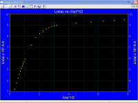
Experimental data for an oxide coated cathode
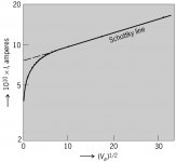
Logarithm of thermionic emission current I of tungsten as function of square root of anode voltage Va. (After W. B. Nottingham, Phys. Rev., 58:927–928, 1940)
The upward slanting is not entirely due to schottky effect - the net flow of current causes resistive I^2xR heating in the oxide layer, not entirely balanced out by the surface cooling effect of loosing energetic electrons.
OK, prove it, with math please; we are talking about physics, not philosophy.
It is time that you stop repeating like a parrot that books say and make a real calculation.
Attachments
Last edited:
These are the very same textbooks you totally dissed earlier in the thread, presumably? 🙄.....contrary to textbooks on thermionic emission
Besides, Popilin's point looks good to me.
Last edited:
These are the very same textbooks you totally dissed earlier in the thread, presumably? 🙄
Besides, Popilin's point looks good to me.
And just which textbooks have I "dissed" earlier in teh thread?
The only comment I made against any textbook was that accepting that the oxide layer is a semiconductor on the basis of Hermann/Wagener is to take an obsolete view that was conclusively shown to be incorrect by later workers.
It's actually Sy that has said multiple times that the textbook writers didn't have accurate knowlege because they didn't have the analytical tools that are available today.
Popilin has provided a graph of anode current vs andoe voltage, showing an upward slope. It's of very limitted value because he's said absolutely nothing about how it was measured or what it was measured on (tube type? static curve or dynamic?) but is roughly in accordance with what I said in my previous post.
He hasn't provided a graph for a pure metal cathode tube which, as I said, would show the assymptote line to be horizontal.
Last edited:
Popilin has provided a graph of anode current vs andoe voltage, showing an upward slope. It's of very limitted value because he's said absolutely nothing about how it was measured or what it was measured on (tube type? static curve or dynamic?) but is roughly in accordance with what I said in my previous post.
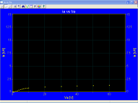
What disappointing, you are not able to interpret a graph, I posted two of Ln(ia) vs √Va, one for the oxide coated cathode of my poor 5R4GY, and other for a tungsten cathode.
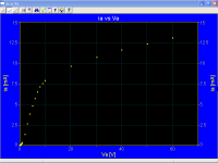
Here is the corresponding graph for ia vs Va, again for my 5R4GY
BTW, the graph is self-explanatory, maybe you need the name of the seller... 😀
Please tell me Keit, have you been in a lab ever?
He hasn't provided a graph for a pure metal cathode tube which, as I said, would show the assymptote line to be horizontal.
Unbelievable! With all due respect, your attitude is pathetic, what is tungsten for you?
Note that Schottky effect is also shown in pure metals, in flagrant contradiction with what you say.
BTW, you still not answer my request. 🙄
The upward slanting is not entirely due to schottky effect - the net flow of current causes resistive I^2xR heating in the oxide layer, not entirely balanced out by the surface cooling effect of loosing energetic electrons.
OK, prove it, with math please; we are talking about physics, not philosophy.
It is time that you stop repeating like a parrot that books say and make a real calculation.
Attachments
Last edited:
What nonsense Popilin writes. He gives a graph puporting to be of a 5R4GY, the same graph more than once, the 5R4GY being an oxide coated type, but he's provided no graph for a pure tungsten tupe, nor mentions the pure tungsten tube type number.
Meanwhile anyone who cares can, of course, look up the datasheet for the pure tungsten type A2087, or an AV44, or any pure tungsten type. Due to the intened application, the datasheets give curves of anode current vs voltage. And they assymptote horizontally - no schottky effect visible. No schottky effect is possible in a pure metal cathode as I said - it depends on an electric field, which is negligible in a metal (metal being a good conductor).
Popilin repeatedly comes back and claims I don't know anything, but never directly addresses the questions raised.
Popilin's puported measurements are a little too good to be true anyway. As anyone who has tested emission on a tube tester knows, when you operate an oxide cathode near, at, and beyond saturation, the reading changes while you watch it - because oxide cathodes cannot sustain saturation.
If meauring by means of a manually adjusted variable power supply, the result you get depends on how fast you do the test, and its not monotonic - you get a different result going up and going down. You don't get a neat fit to a straight line because of ohmic heating in the oxide layer partially opposed by electronic emission cooling at the surface. Thermionic emission, by imparting energy to electrons, causes cooling similar to evaporation cooling.
[The radial electrical resistance of the oxide layer can be calculated from
R = k1 x exp[k2 / (kB Tc)] x Dcoatrad/Lcoat
where
R is resistance in ohms;
k1 is a constant depending on the oxide, typically 1.35x10^-4 ohm.meters for standard barium oxide+strontium oxide mix;
k2 is a constant depending on the oxide, typically around 1.38x10⁻¹⁹ J;
Tc is the median coating temperature, typically 1050 K;
kB is Boltzman's constant, 1.381x10⁻²³ J/K
Dcoatrad is a geometrical factor of the oxide layer cross section, dimensionless;
Lcoat is the length of the oxide layer (length of cathode), m
For a round cathode,
Dcoatrad = Ln[Do/Ds]/(2.PI)
where Do is diameter of emissive surface;
Ds is diamater of cathode sleeve.
Engineers accustomed to calculating the resistance of various engineering shapes will recognise where that formula came from - if not, look up radial resistance of a cylinder in your favorite handbook ]
Of course Popilin has been conspicuously silent on how he did the test. Pulse tested in a curve tracer? Manually using a variable power supply? Computer controlled GPIB voltage source? Each will give a different result. No detail. No credibility at all.
Last edited:
Popilin should note that if schottky effect was applicable in pure metal cathodes, then noise diodes such as the A2087, CV2171, C172, etc would have been much less useful and most likely would not have been made.
These diodes were made and widely employed precisely because the anode current beyond thermionic emission saturation assymptotes to a horizontal line with no sign of schottky effect upward sloping. This means they can be operated at an anode voltage well beyond saturation, so there is negligible space charge. Negligible space charge in turn means the RMS noise output is entirely shot noise precisely determined by the DC anode current, so the device is self calibrating.
As anyone who has spent time in a lab testing prototype radio receivers would know.
If schottky effect applied to pure metal cathodes, you could not get rid of space charge (which smooths out noise) and then noise diodes would not be self calibrating (or at least you could not know you had the anode voltage high enough) - they would be worse than a gas discharge tube, which at least makes plenty of noise, albiet not self calibrating.
Last edited:
(After W. B. Nottingham, Phys. Rev., 58:927–928, 1940)
{Title: Remarks on the temperature dependence of the work function of tungsten}
This journal is not accessible to me at home, and thus most likely not accessible to most users of diyAudio.
Care to post at least the relavent page or paragraphs, so we can assess the context?
The paper attracted a reply, which may or may not be a criticism of it - I cannot acess that from home either.
Oh, only perhaps broadly sweeping aside the best single reference on oxide cathode emission that stands......And just which textbooks have I "dissed" earlier in teh thread?
................🙄Keit said:I am familiar with Hermann/Wagener.......... quite a bit of the theory is out of date.
Oh, the coverage of Hermann/Wagener is splendid.
The English translation (by P S Wagener) came out in post-war, in 1951. The German text was begun in 1938 but put aside during World War 2 and didn't come out until 1944. However, if you read the text carefully, you'll see that much of it goes back well into the 1930's - much of it a compilation of notes Hermann had written years before. Sure it has a very sparse scattering of war-time advances like magnetrons and certain mercury vapour rectifiers taked on, but t's basically a 1930's text.
Look at the references cited at the end of each chapter - most are dated in the 1920's and 1930's - only a few dated in the 1940's.
Sorry to tip your boat, but research into vacuum tubes did not stop in 1938, nor did it stop in 1944. Not untill the transistor age (mid 1960's on) did tube theory advancement slow down. Herman/Wagener was a good reference when the original German was written. By the 1960's much of it was obsolete.
Sorry to tip your boat, but if you want a better understanding of tube theory, you cannot confine yourself to one book, you have to look up papers covering the varuous aspects.
The "up to date" tube types used in examples, eg AC2 in Fig 44, introduced 1935 also indicate its obsolescence. Tube manufacture, tube service life, and tube performance, was very different in the immediate post-war years than in the 1930's.
Would you base your understanding of how transistors work on the transistor physics texts that came out in the 1950's - when manufacturers thought a current gain of 50 was pretty good? Certainly the likes of Texas Instruments and Fairchild did not - by the early 1960's they were using silicon planar technology to make transistors with current gains of over 1000. And by the late 1970's Fairchild and National Semiconductor beat even that by a couple of orders of magnitude. But when I was at university, the solid state physics textbook explained in some detail why current gains over about 50 to 70 just were not possible! And why not was an exam question!
And, it seems, some folk take information out of Hermann/Wagener only half understood, or they take it out of context.
Still, on page 86 of Vol 1, it does confirm what I've been saying - anode current in a pure tungsten cathode tube shows, unlike an oxide type, that "a definite saturation point" is seen , that the current thereafter is a closely horizontal line. It also says on page 86 that heating of the coating accounts for some of the upward trend in current in oxide cathode types. A later section covers oxide layer heating and cooling in greater detail.
Last edited:
No schottky effect is possible in a pure metal cathode as I said - it depends on an electric field, which is negligible in a metal (metal being a good conductor).
This is the third time that I say it; you must evaluate the electric field at the surface of the conductor.

Popilin's puported measurements are a little too good to be true anyway.
Thanks. 😎
The key point in order to not going crazy with permanent change of multimeter lectures is an extremely well regulated PSU for the filament, anode voltage was provided with batteries, that's all.
[The radial electrical resistance of the oxide layer can be calculated from
R = k1 x exp[k2 / (kB Tc)] x Dcoatrad/Lcoat
where
R is resistance in ohms;
k1 is a constant depending on the oxide, typically 1.35x10^-4 ohm.meters for standard barium oxide+strontium oxide mix;
k2 is a constant depending on the oxide, typically around 1.38x10⁻¹⁹ J;
Tc is the median coating temperature, typically 1050 K;
kB is Boltzman's constant, 1.381x10⁻²³ J/K
Dcoatrad is a geometrical factor of the oxide layer cross section, dimensionless;
Lcoat is the length of the oxide layer (length of cathode), m
For a round cathode,
Dcoatrad = Ln[Do/Ds]/(2.PI)
where Do is diameter of emissive surface;
Ds is diamater of cathode sleeve.
Engineers accustomed to calculating the resistance of various engineering shapes will recognise where that formula came from - if not, look up radial resistance of a cylinder in your favorite handbook ]
Nice try, but this is not what I asked for and this does not prove anything; on post#237 you did a claim that must be proved.
Popilin should note that if schottky effect was applicable in pure metal cathodes, then noise diodes such as the A2087, CV2171, C172, etc would have been much less useful and most likely would not have been made.
I cannot see any horizontal curve
http://frank.pocnet.net/sheets/084/a/A2087_GEC.pdf
You are confused by a scale factor, very common mistake. 😉
Make the curves with current expressed in µA and you will appreciate the correct slope, manufacturer did not this by the way.
Last edited:
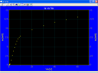
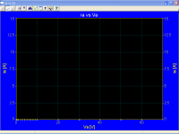
Just to avoid complains about the scale factor issue, here are the plots, exactly the same data, but different scale factors.
ia expressed in mA

ia expressed in cA

ia expressed in dA

ia expressed in A

All data are available to anybody who need them, I also could provide a link to a demo software.
ia expressed in mA
ia expressed in cA
ia expressed in dA
ia expressed in A
All data are available to anybody who need them, I also could provide a link to a demo software.
Attachments

OK, I think I understand now. When it supports your point it's current, if not it's out of date and safe to ignore ? Right, that's easy then 🙄Still, on page 86 of Vol 1, it does confirm what I've been saying.....
Yes, it can matter.This is the third time that I say it; you must evaluate the electric field at the surface of the conductor.
Apparently so. Seems Au- can form bona fide ionic solids with specific metal cations such as Ba and Cs, with weak conductivity, resembling semiconductors in terms of bandgap in the case of CsAu. Platinum apparently shares some of the 6s shell affinity and behaviour with Au. So I continue to be curious about chemisorption of BaO and gold.Bands. These are solids, so the non-core electrons are delocalized.
Here's full text of an article which seems relevant perhaps:
Effects of relativistic motion of electrons on the chemistry of gold and platinum
Abstract:
Effects of relativistic motion of electrons on the chemistry of gold and platinum Martin Jansen Solid State Sciences Volume 7, Issue 12, December 2005, Pages 1464–1474
Experimental evidence proving the unique stabilization of the 6s orbital in platinum and gold is presented. The conclusions are drawn from the chemical reactivities, of both elements, as well as from structural and spectroscopic features of selected compounds. In particular, the opening of a band gap in transparent CsAu and Cs2Pt, backed by band structure calculations, are regarded conclusive indications of Au− and Pt2− to exist as closed shell species in these compounds.
However, I readily admit I am a kook at this level of chemistry, can't make any sensible comments really.
Last edited:
This is great, I've got the hang of it in no time 🙄 😀That's out of date and safe to ignore. 😀
This is the third time that I say it; you must evaluate the electric field at the surface of the conductor.
Bang you head again, Popilin. Try bricks instead of polystyrene - might make you feel better.
You have no idea how to apply the math. You talk about the field at the surface, but the field terminates at the surface. You haven't accounted for tube geometry anyway. Visuallise the field as lines of flux (flux lines normal to lines of constant potential) - for a typical cylindrical tube the flux lines are concentrated at the inner surface, the same as spokes of a wheel are concentrated near the hub. Your math does not appear to account for this.
This is partly why I asked you to concisely describe your term Va, which you have never done.
I have no idea what that is supposed to mean. Permanent change of multimeter lectures????The key point in order to not going crazy with permanent change of multimeter lectures is an extremely well regulated PSU for the filament, anode voltage was provided with batteries, that's all.
Presumably this is in reference to you post after that where you asked for proof that net emission current causes heating of the oxide layer.Nice try, but this is not what I asked for and this does not prove anything; on post#237 you did a claim that must be proved.
There is no need for proof - it is described in textbooks on thermionic emission, it is self evident that as the oxide layer is not a metalic conductor it must have a voltage drop normal to the net current flow (ie radially), thus P = IxV. I gave you the standard formulae and constants for standard barium oxide + strontium oxide mix, so you can calculate the apparent radial resistance and apply P = I^2R.
You must be blind or have bent eyes then.I cannot see any horizontal curve
You are confused by a scale factor, very common mistake. 😉
Make the curves with current expressed in µA and you will appreciate the correct slope, manufacturer did not this by the way.
What nonsense is this? microamps or milliamps, or whatever units you like, it makes no difference, the shape is the same.
Just to avoid complains about the scale factor issue, here are the plots, exactly the same data, but different scale factors.
What nonsense is this? Why do you do these silly repetitions?
If you look at, say, the Vf = 3.5V line in the A2087 datasheet plot of Ia vs Va,. we see that the line is substantially horizontal once the emission saturation pioint is past. Quite unlike a typical oxide cathode tube plot.
For Va 75V to 200V, the actuall variation shown is from 4.95 mA to 5.3 mA, a variation of 7%.
In comparison, in your black&white plot in your post #242 pupporting to be for a tunsten cathode tube, the varation is 15%. 15% is a long way from 7%!
In the first plot in your post #252 (for which abolutely no details are given as to where you got the data from, typical for you), the voltage range is different, but we can scale back the 75V to 200V range back 60V & 22.5V. For this range, visually about as far on a proportiona basis from the saturation point, we see that the variation in current is from 10 mA to 13 mA - a variation of 30%!
Clearly, whatever that plot is supposed to be for, it isn't for a pure tungsten cathode tube.
And, equally clearly, if anone was misled by the datasheet scale, it wasn't me - perhaps it was you. Are you seriously suggesting the manufacturer used an inappropriate scale?
You repeated the plot several times at different scales. Why? It proves nothing. They are just progressively more useless as the plot range becomes too small to read.
The question may arise as to just why the current as plotted by GEC increases from 4.95 mA to 5.3 mA over an anode voltage increase of 125V. This increase is insignificant for the intended application, but it is a slight increase.
One important factor is the the anode cylinder does not fully enclose the filament/cathode. For practical construction reasons, a few mm of filament projects out each end of the anode. Som the electric field in the vicinity of the ends of the filament is less than in the centre of the tube structure. Thus emission saturation occurs at a higher voltage at the ends of the tube structure than in the centre.
Thus tube geometry is responsible for the gradual transistion form the three-halves region to the saturation region, and for the further slight increase in current for increasing voltage.
Support for this explanation can be seen in the plot for the AV44 regulator diode. This is also a pure tungsten cathode tube, but with a higher ratio of anode length to anode diameter, and no filament projection beond the anode ends. Sure enough, the change in current past the saturation point (use an anode voltage rage of 37.5 V to 100V - same proportion as before) is significantly less, due to the end effects being proportionately less (and the transition from three-halves to saturation is noticeably sharper). If schottky effect was responsible for the increase per your theory, it should be the same proportionate change. That's not what we see.
There's another minor reason for the gradual transition and small upward creep in current - Both the A2087 and the AV44 have cylindrical anoides coaxial with teh cathode/filament. So, saturation begins with the space charge not equally dense in the radial sense.
There still are end effects in the AV44 of course. To render end effects negligible, we woud need a very long tube structure. Evidently this was what was used in the curve tracer plot shown on page 65 of Hermann/Wagener Vol 1 page 86, which shows a very sharp transition into a horizontal line.
Better bang your head against the bricks again, Popilin, your understanding of tubes is still faulty. Bang it hard. Your application of math is still faulty.
Be sure to apply the common sense test. Electrons are either in the metal or in the electric field. If they are in the metal, they are outside the field, so the field has no effect. If they are in the field, they have alraady been emitted (by virtue of the cathode temperature supplying the necesary energy).
When your headache goes, get in the lab yourself and do a few measurements - something that it appears you haven't done yet. Be sure to carefully design the experiment.
Last edited:
OK, I think I understand now. When it supports your point it's current, if not it's out of date and safe to ignore ? Right, that's easy then 🙄
Can we have some sense in this thread? You are being silly.
Not everything in the book is superseded, and I never said it was.
What I did say is that the view that the oxide layer is a semiconductor (per Hermann/Wagener Vol 2 Chapt 4 Sect 19 page 156, supported by 3-16) was shown later to be incorrect.
It was shown to be incorrect by Hensley E B, Conduction mechanism in oxide-coated cathodes, Journal of Applied Physics Vol 27(3) March 1956, pp286-290.
The first sentence in the first paragraph is:
"Prior to 1949 it was generally believed that the conductivity of oxide-coated cathodes could be adequately accounted for on the basis of the alkaline earth oxides being n-type semiconductors."
After some description of experimental apparatus, Hensley goes on in detail why this is not so.
Note that Hermann/Wagener, although published in English in 1951, is essentially a 1930's text.
Not that any of this has anything at all to do with why gold is used to plate control grids in some tubes, of course.
- Status
- Not open for further replies.
- Home
- Amplifiers
- Tubes / Valves
- Why Gold Grids