@cm6
Thank you. The problem is the woofer only works few kHz, until 2.2 kHz. That ferrite begins to be effective from 150 kHz (unlike the usual cheap ones, 1 Mhz).
With the tweeter (first order filter) causes an unpleasant increase in treble.
Maybe I'm not reading it correctly but figure 10 in the paper shows an increase in distortion of almost 30db at 1KHz.
The ferrite bead works great at suppressing the switching frequency up at 150KHz but it also causes a lot of distortion down in the audio band.
True, ferrite beads are much smaller than what you are using but still......

Now the graph is different!
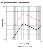
https://uk.farnell.com/wurth-elektronik/74272733/ferrite-core-split-8mm-30mhz/dp/1800423
[PDF] http://www.farnell.com/datasheets/1919956.pdf

Well, there are more info > 30 MHz.
I do not have class D amps, only class AB. Maybe in the future: PURIFI 1ET400A.
https://uk.farnell.com/wurth-elektronik/74272733/ferrite-core-split-8mm-30mhz/dp/1800423
[PDF] http://www.farnell.com/datasheets/1919956.pdf
Well, there are more info > 30 MHz.
I do not have class D amps, only class AB. Maybe in the future: PURIFI 1ET400A.
Attachments
Last edited:
It is frustrating to ignore an explanation of the phenomenon, hence the beginning of this thread, because the first one who is upset is me.
well ether u are up to no good
or
u are highly susceptible to impression
or
you have a stumbled on a phenom that has eluded us all
BTW if its doing even 1/2 of what u say u should market that thing
with a money back garontee
or
u are highly susceptible to impression
or
you have a stumbled on a phenom that has eluded us all
BTW if its doing even 1/2 of what u say u should market that thing
with a money back garontee
Last edited:
This is Maty's thread over on ASR where this started. Danny Richie from GR..
[Video] Speaker measurements by Danny Richie | Audio Science Review (ASR) Forum
[Video] Speaker measurements by Danny Richie | Audio Science Review (ASR) Forum
I just did something similar to a pair of Klipsch rb-51 speakers, in this case there was too much overlap around the crossover area.
I wouldn’t recommend a ferrite on any speaker, amp output or interconnect these days however. A couple years ago I was getting something from doing this on an old Hafler amp, as it must have been oscillating a bit to have made a difference. I no longer use that amp.
I wouldn’t recommend a ferrite on any speaker, amp output or interconnect these days however. A couple years ago I was getting something from doing this on an old Hafler amp, as it must have been oscillating a bit to have made a difference. I no longer use that amp.
And, despite all logic, it works on my two loudspeakers. Hence, I opened the thread because I find no explanation!
- Home
- Loudspeakers
- Multi-Way
- Why does it work? Crossover with RF ferrite (wires) and 10nF polystyrene (bypass)