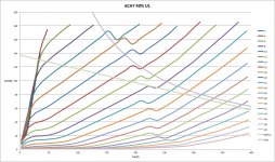
OK..... so here is the same tube with UL 40%, that does not "look" as pretty... I did not expect this to look like this, so I repeated the measurements just to be sure the kink in the area of interest was not a measurement error.
It is difficult to see that any load line will give decent linearity for large signals...
I understand that the optimal UL tap % is very tube dependant, so is this variation not part of an explanation why some amps sound poorly with a standard tap %?
Perhaps an Elder may pass by to impart their wisdom? 🙂
Attachments
Hammond 1628SEA's UL's
Back to the Hammonds,
Quote from Jazbo8: It seems very likely that Hammond reversed the P and B wires
Indeed, I have just checked the primary:secondary phasing and there is a phase inversion when I use the primary "P" (Blu) and secondary "black" (COM) as the reference.
So the primary lead colours are incorrect.😡
For reference the manufacturing date is 8/17/06
"so here is the same tube with UL 40%, that does not "look" as pretty..."
Holy cow! I think the 40% UL boat just burned and sank. With such big kinks in the curves, I would suggest curve tracing the same tube in ordinary pentode mode to see if the tube itself has a significant "kink" problem. But it certainly illustrates the issue of screen grid currents corrupting the transfer.
My opinion of UL is that its a cheap way to put some local feedback into a pentode stage for lowering Zout, but that there are better ways to do it. Local resistive feedback to a driver stage can put more loop gain into it, with better linearity. The UL setup puts non-linear g2 currents into the feedback path.
Even triode mode has some drawbacks (besides less power output). The grid1 V to I transfer has varying power law (not steady 1.5 power law, like the plate) from grid wire proximity effects. This causes mis-tracking with the g2 or plate (1.5 power law) internal feedback, leaving 2nd harmonic dist. and smaller amounts of higher harmonics. Then plate loading makes it even worse.
Last edited:
Well one example doesn't sink a boat. I have an example from the late sixties that is an anathema to many with high GNFB and UL, but it manages 25W at 0.1% THD and 34W at 1% off a pair of EL34s.
Would I try and get UL to work with any other than the usual suspects of El34/6500/KTxx? Probably not, but I also want to try different things now.
Would I try and get UL to work with any other than the usual suspects of El34/6500/KTxx? Probably not, but I also want to try different things now.
The Beam Tetrode tubes would have much lower g2 current (aligned grids) than the pure pentode tubes, so one probably can get away with UL mode there.
Never-the-less, seeing the g2 current show up badly in the plate curves is very disconcerting. The HK Citation II used UL mode with KT88s, but also used plenty of effective local driver stage N Fdbks. I think Bob Carver was the one who commented that Stu Hegeman had said UL mode was a mistake in the design.
On the other hand, I have noticed that aligned grids cause the transfer function for grid2 to drop to a 1.3 to 1.4 power law (instead of 1.5 power law for non-aligned grids). (an anti-proximity, or shielding, effect for g2) This makes the psuedo triode curves mistrack even worse from the g1 grid's power law (which is up above 2.0 power law over a considerable range). Likely accounting for some of the bad press for psuedo triodes versus real triodes. (although most of that is likely just due to the older triodes having lower gm and less grid wire proximity problems to begin with.)
UL --- final burial, RIP
There are multiple ways to do local feedback to the driver stage, instead of "shaky" UL mode. R feedback to the driver grid (crossed for P-P case), to the driver cathode, or the driver plate (Schade Fdbk). And then combo's of those, such as used by the Cit II or the RCA tube handbook 50 Watt Amp.
But it occurs to me that what most of us really want, is to make the output tube act as a triode, without sacrificing any power output, and low distortion too.
So why not just do it right.... Attached is a circuit to make the output stage V2 act just like triode V1. An emulation circuit essentially. Plug any high Mu triode into V1, and the output V2 just copies it. Could work for SE or P-P. V2 still operates in pentode mode, with a fixed +Vs on grid 2, but it behaves as V1.
V1 is used in inverse triode mode to serve as the local N Fdbk attenuator. In order for V1 to operate at constant current, its plate must behave as -Mu times Vin. Any deviation from the Mu rule, and the Mosfet Q1 (and its Gyrator load) instantly corrects the grid drive to V2 to obtain that. One could put an additional R attenuator in the V2 plate to V1 plate feedback path to accomodate lower Mu tubes for V1 too. One could also look at this as a voltage mode Schade N Fdbk circuit, instead of the usual current mode Schade setup.
Attachments
Last edited:
The question of triode vs UL is one of those topics that has no end.
IMHO the most important is the topology.
A good topology, either with a triode or UL will sound great.
Recently, I changed my "Deuce" amp for triode operation and it played very well with my speakers that are horn (L300), but as I moved back to UL it played much better, with more dynamics and less distortion.
This is because mr. Stu Hegeman project was to work as a UL, not as a triode one, the negative feedback alters completely when changed one to another. There is a typical 30dB with UL, how much do you think will be on triode? I think a lot more.
Some say that he did it because Harman asked him to build a powerfull amp (60W instead of 30W on triode) to compete with others of the time, but I'm sure that if the topology were designed to work better at triode he had just installed a switch to change it UL or triode at the rear of the amp, what I did in less than 30 minutes.
here two good readings about this theme
http://www.aikenamps.com/images/Documents/Crowhurst_blocking.pdf
http://www.aikenamps.com/images/Documents/UL.pdf
Last edited:
Interesting idea. As there is nothing new under the sun, do we know if this has been tried successfully before, or has it previously been dismissed due to evil sand?
There was a Japanese site that had actual tested circuits, where a triode was used in inverted mode for N Feedback. I don't recall them using this particular implementation. But they had numerous variations on the theme, and I haven't looked at it again in years.
There is always the question of stability when one closes a loop with gain in it. But that should be manageable with an RC dominant pole inserted, if the main components don't already provide that.
I had suggested the idea a long time ago for the global N feedback network of a SS amp (or Tube Amp) to give it a single tube SET sound. Probably never got tried. Some complaints were made about messing with the N Fdbk network too casually. (ie, tube swapping)
I HAVE seen a tube Amp schematic where the global N feedback was taken back to the screen grid of the input tube (instead of the cathode), so the internal tube Mu was used similarly for enforcing SET sound. This also got some negative comments about being non-linear Fdbk. (Probably by the same people that use UL all the time.)
There are always those who will complain about anything "sand" related in an Amp design. The point though is about doing something interesting to see if it works. N Fdbk can do most anything. More people need to play with it.
Last edited:
I hesitate; it might be that it is too early in the morning here - but the latest posts seem to go somewhat contrary to what has not only been found ever since U.L. re-appeared all of 65 years ago, but has been widely publicised ....
[There are numerous practical amplifier tests, graphs from several tube manufacturers of power output, distortion, Rp, etc. vs % screen taps going from pentode to triode. In addition the analyses of Hafler and Keroes, Walker and Williamson, extensive analyses by F. Langford-Smith of RDH-4 fame and another (in 1950 if my memory serves) - to name only a few definitive reports among many others ....]
Respectfully, I find it somewhat difficult to reject all that disagrees with the last few posts. Firstly it often seems not to be grasped that external feedback - Schade or whatever - cannot be directly compared to UL. With external feedback the tube still has pentode characteristics with its pros and cons, just as a triode with external feedback basically retains triode characteristics with ... etc. The distributed loading of a pentode 'creates' a third kind of tube, with its pros and cons; i.e. in practice retaining most of the desirable characterisitcs of both types for a certain G2-percentage range.
The mentioned classic graphs published by G.E. for the KT88 (internal parameters vs. % screen tap) are a general example; others are similar. So what is the problem with that - particularly, to repeat, in the light of so many practical designs supporting those?
Ufudu, I am not familiar with your curve tracing programme, but respectfully your graphs differ from the general. I have never seen the kink you found in any other graphs, and also not the deduced distortion which would arise from the same. As said before, I have not reread the rest of the thread before recent posts and apologise for any repetition. I am simply unable to now suddenly find condemnation of the distributed load topology, having also built, measured, listened to etc. such products. For me it would at least need some refutation of previous findings, not simply alternative arguments, to make me change my mind. I think such a stance is scientifically fair?
I'll throw a little fuel on the fire. 
UL has been called partial triode. In any event, it's a form of local NFB. It's a fact that full pentode mode exhibits the lowest open loop distortion, when g2 B+ is regulated at some fraction of anode B+. "Custom" O/P "iron" containing a separate screen grid winding set to 1 of the popular UL % allows both regulated g2 B+ and UL feedback, simultaneously. The technique does work. While such magnetics are costly, they allow excellent use of sweep tubes containing fragile screen grids.
UL has been called partial triode. In any event, it's a form of local NFB. It's a fact that full pentode mode exhibits the lowest open loop distortion, when g2 B+ is regulated at some fraction of anode B+. "Custom" O/P "iron" containing a separate screen grid winding set to 1 of the popular UL % allows both regulated g2 B+ and UL feedback, simultaneously. The technique does work. While such magnetics are costly, they allow excellent use of sweep tubes containing fragile screen grids.
Last edited:
Naughty, naughty...😀I'll throw a little fuel on the fire.
Don't think this issue will ever be "settled", some people like it, some people don't - whether on technical and/or subjective grounds. I am in the camp that says "to have your cake and eat it", would require a separate winding for the screen grid, not simply tapped like 99% of the UL OPT's currently on the market...
We also have to bear in mind that "ultralinear" is a marketing term, not an electrical one.😉
Perhaps an Elder may pass by to impart their wisdom? 🙂
This looks like an instrument anomaly, not the tube. In many measurements, range shifting can cause that.
This looks like an instrument anomaly, not the tube. In many measurements, range shifting can cause that.
It has to be something with the setup on the uTracer. Normal UL characteristic should be similar to the one shown below:

This looks like an instrument anomaly, not the tube. In many measurements, range shifting can cause that.
Agreed, it does look like a range change... I was planning to investigate this further....
OK, something odd is going on with the measurements.
Firstly I upgraded to the latest GUI from Ronald Dekker's site. Then if I replicate Jazbo8's GUI settings I get similar smooth curves (no kink)
However when I replicated my own previous settings, and the kinks were still there.
So, to be able to zoom in onto the kinky area, I ran the tube in pentode mode with Vs=400V and swept Va to 300V. But, I discovered, the kink's appearance is dependant on the uTracer's sweep start voltage, with Vstart>85V = no kink, with Vstart<80V the kink appears! The traces take one of 2 paths, the upper is with lower start voltages and the lower one with the high start voltage. I would guess that the lower trace is the correct one, since it meets up with the upper trace after about 275V. Screen current has been included. The trace overlays are as a result of using different sweep start voltages.
Unless I am doing something really stupid, there could be a problem with the uTracer? Perhaps Jazbo8 can replicate my settings & confirm.
Apologies, I did not intend to hijack this thread, if it warrants it I will create a separate thread.
In the meantime it may be best for the mods to delete my previous graphs.
Attachments
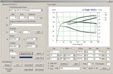
Jazbo8's illustration is quite nice. However, something is fishy there too. The pentode knee starts at 160 mA (k = 0), but at k = 0.4 it has dropped to 80 mA. This would imply only 25% as much power output for 40% UL.
Is the uTracer measuring screen grid current and then combining that, at k effectiveness, with the plate current in software?
Is the uTracer measuring screen grid current and then combining that, at k effectiveness, with the plate current in software?
- Status
- Not open for further replies.
- Home
- Amplifiers
- Tubes / Valves
- Why do some people dislike ultralinear?