It is not, it's neither a triode nor a pentode.But U/L is still pants..
The 211 is a power triode transmitting tube.Here is the new Ongaku with U/L silver wound Op Tx.
It is not, it's neither a triode nor a pentode.
The 211 is a power triode transmitting tube.
It was meant as a laugh..(Joke)
But and I am serious I do not like U/L. Don't get me wrong its OK if it rocks your boat! If I have switching capability it is rarely used..
OK its neither a triode or a pentode so its something else..I don't like the something else. Perhaps its a FET...😀
Regards
M. Gregg
Last edited:
😕
But U/L is still pants..
Regards
M. Gregg
Yes, it's the biscuits in your knickers!
"its neither a triode or a pentode so its something else.."
ANSWER: all of the above (see below)
The usual triode formula: Ip = G[Vg1 + Vp/u]^1.5
For k factor UL mode (AC formula): Vg2 = k Vp
and using the internal pentode Mu for g1 versus g2 as: u21 (ie, the effectiveness factor for Vg1 versus Vg2)
then: Ip = G[Vg1 + (k*Vp)/u21 + Vp/u] ^1.5
for constant current: [ vg1 + k*Vp/u21 + Vp/u ] = constant
re-arranging to get an effective MU = 1/ [ k/u21 +1/u ]
so now UL is equivalent to a triode with the effective MU:
Ip = G[Vg1 + Vp/MU ]^1.5
So the tube's effective MU in UL is:
1/ [ k/u21 +1/u ]
changing k from 0: so effective MU = u (the usual pentode case for k=0)
to k =1: MU = 1/[ 1/u21+1/u]
u for the pentode plate is large, and 1/u is tiny, so effective MU = approx. u21 (the usual triode case for k=1)
It should be apparent that ALL cases of k are effectively triodes (pentode, UL, & triode).
k just varies the effective triode MU between pentode and mu internal.
All pentode curves are the remnants of an effective triode, which has had its plate zero current point moved into negative plate V territory (on graph), from the effect of the +DC bias on the screen grid. (Positive screen grid is acting as a surrogate for + plate voltage) The plate curves would converge to a point in neg. Vp territory, if the screen grid didn't eat the plate currents for Vp less than Vg2.
(ie, one could extend the pentode curves by drawing lines left from all the flattish pentode saturation regions, to an imaginary point at some -plate V and zero plate current. )
UL just changes the effective MU of the hidden triode.
And screen grid voltage for a pentode just shifts the hidden triode curve set to the left by u*Vg2/u21. (with grid2 consuming the plate currents to the left of Vp < Vg2)
So all these arguments about which sound better are -almost- superfluous.
Just screen grid current remnants affecting the hidden triode at large signal amplitude.
Everything is a triode. Just more or less Mu and truncated curves at lowish Vp.
OK, lets NOT start throwing biscuits around now. I'm out of here. Shields up! Max warp speed Scotty!
Last edited:
"its neither a triode or a pentode so its something else.."
ANSWER: all of the above (see below)
OK, lets NOT start throwing biscuits around now. I'm out of here. Shields up! Max warp speed Scotty!
Great,
But Triode doesn't sound like U/L pentode.😀 (assuming the same output Tx is used).
so what happens when you put a diode in the U/L connection? Lets assume .7V across the junction..the voltage drop is I guess neither here or there its just a VD similar to being across the tap of the Tx (just another .7V).
NB What about back EMF effects for U/L vs pentode triode? (A few more crumbs but interesting non the less..😀)
The effect of triode connection is very pronounced on signal tubes e.g EF86 etc..these don't have the problem with Op Tx EMF well not directly..
So if its just MU the MU seems to have an effect on harmonic..ie the woolly triode OK we are into sheep..😀 or the Cyber razor cut sparkly pentode..
The reason I mention this is because the Old protection of parallel diodes to protect the output tube removes (changes the sound ie less woolly) of the O/P tube.
Ie its supposed to remove/reduce the effect of back EMF spikes. (Trouble is if the diodes short it damages the O/p Tx)..
😀 but that's another issue..Although the effect is similar to the U/L diode..obviously if it goes short and the resistor is in place.
Never though about it until now U/L connected coupling Tx..LMAO
Regards
M. Gregg
Last edited:
I just thought its an interesting issue,
The idea of wound components and their "sound signature"..(EMF)<<warm sound..Low Frequency limitation.
Reminds me a bit of the old transistor circuits with transformer coupling.
Sorry I digress..😀
Regards
M. Gregg
The idea of wound components and their "sound signature"..(EMF)<<warm sound..Low Frequency limitation.
Reminds me a bit of the old transistor circuits with transformer coupling.
Sorry I digress..😀
Regards
M. Gregg
Last edited:
Without straying off topic re: "eletron stream"NB What about back EMF effects for U/L vs pentode triode?
 - the back EMF effect is inversely proportional to the damping factor.
Without straying off topic re: "eletron stream"
OK,
But what is the audible effect of EMF..and reducing or removing it?
In both triode and U/L.<<is one more pronounced than the other?
I assume Mr Miller is a non player in this arena..
Regards
M. Gregg
Last edited:
Triode has higher damping factor than UL and pentode, so it is the least effected by the back EMF, i.e., it is better damped which results in less "boom", some like it, but other may miss the extra boost given to the LF, at the end, it still comes down to personal taste and the speaker used with the amplifier.

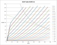
Nice, good to see the kinks straightened out. I'm surprised g3 would make that much difference, but the collected charge on it must have really gone wild.
Could you run the 60% case again too? Oh, and the B+, 400V?
Could you run the 60% case again too? Oh, and the B+, 400V?
Last edited:
I don't think the uTracer supports Eb>300V, so here is one done with the SPICE model, it should be close enough.
An externally hosted image should be here but it was not working when we last tested it.
Thanks.
I was just wondering what the B+ was on Ufudu's 6CA7 graph. 300 V is fine. I'm just curious to see the g1=0V "knee" V change versus UL% for the real tube.
Hmm, now that I think about it, that data is already on the standard plate curves (versus Vg2). Just have to calculate the B+ minus (B+)UL% to get the Vg2. So the UL mode knee is just moving down the plate curves (versus Vg2) graphs. hmm, not that simple, depends on how far the plate can pull the load down.
Last edited:
Of all the amps I have built so far, the best ones were push-pull DHT stages with well filtered B+ supplies, or PP pentode stages with G2 voltages far below B+. My sims showed that UL stages did offer lower overall distortion but only for lower order components, higher order components become much more prominent. Also, a PP pentode stage with regulated G2 is far less susceptible to B+ ripple inter-modulating with the signal because of its high plate resistance, again confirmed with simulation. Interestingly, this advantage is nullified when using plate-to-grid (Schade) feedback because the B+ ripple is now fed into the driver stage.
My 807-based pentode-connected Williamson sounded far better than I expected. Originally that amp was going to be UL but I switched it to pentode because B+ was too high to put on 807 screens. It was a total revelation and made me question all the various audio fads and orthodoxies about amp design.
Personally, I think the success of UL has nothing to do with sound quality and everything to do with economics.
Last edited:
Interesting comments. Very sensible. The later uTracer curves convinced me that UL has nothing obviously wrong (I was expecting bad g2 current issues), but now it's down to an FFT or listening to tell the difference. The hidden triode model indicates that UL should be using more like 2X (to even 4X) the primary Z OT at 40% UL (versus pentode), which is way more than the traditional advice for UL. I'm now wondering if that is the reason for the higher harmonics seen. Not very enticing to use UL, if the OT has to be that high of Zprimary.
Schade does have the problem of B+ referencing for the N Fdbk as you say. Similarly for the other partial Fdbk schemes (except CFB or related). Wavebourn had suggested a SS assist there, using a P type device at B+. A couple of variants are possible. Basically measure the B+ to plate voltage and send current feedback to the driver. PSRR greatly increased. A differential driver (for P-P case) would also remove the common mode B+ related portion of conventional Schade or partial Fdbk. A regulated B+ and Vg2 are always a big improvement as well.
Schade does have the problem of B+ referencing for the N Fdbk as you say. Similarly for the other partial Fdbk schemes (except CFB or related). Wavebourn had suggested a SS assist there, using a P type device at B+. A couple of variants are possible. Basically measure the B+ to plate voltage and send current feedback to the driver. PSRR greatly increased. A differential driver (for P-P case) would also remove the common mode B+ related portion of conventional Schade or partial Fdbk. A regulated B+ and Vg2 are always a big improvement as well.
Last edited:
The quotation " The distortion from UL is lower than for triode mode or pentode mode" and the graph posted by Merlin come from the Fritz langford Smith and AR Chesterton Ultralinear articles from Radiotronics magazine. Radiotronics was the factory "tech bulletin" from the Sydney Australia AWV tube factory where Fritz was chief engineer. His other significant job there was as editor of the Radiotron Designers Handbook.
Most if not all the Radiotronics stuff is on-line here:
electron Tube Data sheets - AWV, Amalgamated Wireless Valve Company
The UL Articles run over 3 issues from May 1955 to July 1955.
Wireless World did a UL article in August 1955 for which I haven't found a link.
The distortion being lower than for triode mode or pentode mode can be clearly seen in many EL84 datsheets.
I will continue to use UL, mostly in conjunction with some cathode feedback or balanced shunt feedback from the output tube anodes. Why? Because I've never built anything which SOUNDED better and amps I've built and tried in triode/UL/Pentode mode invariably ended up in UL mode. Also that combination of UL + cathode or balance shunt feedback gives a sufficiently low damping factor that global feedback is not required. In addition to that, the lower effective rp of the output tubes better drives the leakage inductance and shunt capacitance of the output tranny shifting the 2 high frequncy rolloffs higher and also better drives the primary inductance thus shifting the low frequency roll off lower (these last claims could also be made for triode mode).
Two other things from the Radiotronics articles:
1) It was stated that leakage inductance compensation was REQUIRED, that is, a cap or RC network is required between anode and screen connections. This was then ignored by many designers of UL amps.
2) It was also stated that the distortion in UL mode was lower than could be accounted for by feedback theory alone.
Cheers,
Ian
Nice, good to see the kinks straightened out. I'm surprised g3 would make that much difference, but the collected charge on it must have really gone wild.
Could you run the 60% case again too? Oh, and the B+, 400V?
Yes B+ is 400V (latest uTracer version has hardware to support 400V)
Here are the 60% curves.
Attachments
Gingertube,
As said in your post #358. Just to remind that any cathode feedback is partly UL, or at least distributed load. So one could just as well use the 'screen-to-B+' winding as the cathode winding, only that then requires an often impractically high G1 input signal. I notice that some designers split the difference, using both a lower cathode winding ratio plus low UL taps to make up the difference (but that brings back the problem of high screen voltage).
As said, another problem is that different output tubes require different 'optimum' taps than shown by the Langford-Smith graphs (e.g. KT88). And then, as if there are not enough gremlins, I find an unacceptable spread in parameters of same number tubes these days. Not to open another "can-o' " - what a world. Still.
Ufudu,
Ouch! Who would have expected that! Glad you came right ar last. We should meet sometime.
- Status
- Not open for further replies.
- Home
- Amplifiers
- Tubes / Valves
- Why do some people dislike ultralinear?