
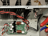
The extra caps, are they for smoothing out the power demands of the amps when they need higher power or are they filter caps for ripple and what not?I also just received a 630-G with the same auxiliary and driver voltages but with +/- 61 VDC rails, have yet to try it out though as I was waiting for parts for my extra capacitors PCB which just arrived. I only plan on using one module with this supply.
Having the 12 volt aux. supply is nice to have. I kind of wish Icepower would have put a 12 volt aux supply in the 1500. It would have made powering the DSP much easier and I can't help wonder if the amps would run better if they where getting 12 volts as the amps data sheet say is the proper voltage. The 1500 gives you 7 volts. It works with 7 volts but it is below the min. voltage in the data sheet. Go figure.
The extra caps, are they for smoothing out the power demands of the amps when they need higher power or are they filter caps for ripple and what not?
Having the 12 volt aux. supply is nice to have. I kind of wish Icepower would have put a 12 volt aux supply in the 1500. It would have made powering the DSP much easier and I can't help wonder if the amps would run better if they where getting 12 volts as the amps data sheet say is the proper voltage. The 1500 gives you 7 volts. It works with 7 volts but it is below the min. voltage in the data sheet. Go figure.
The extra caps prevent bus pumping -> https://www.maximintegrated.com/en/design/technical-documents/tutorials/4/4260.html. You can see the issue in the frequency response measurement (both with and without extra caps) in this post -> https://www.diyaudio.com/community/threads/why-do-i-have-56v-on-my-vdrive.383620/post-7038350. That measurement is somewhat worse case as it is one channel driven and I have the modules setup so that each module drives left/right and the inputs are wired with opposite to polarity which helps cancel the bus pumping. I went with extra caps as at least one other DIYer experienced bus pumping when using a non-ICEpower power supply -> https://theslowdiyer.wordpress.com/2022/01/30/second-chances/ so wanted to make I was doing everything I could to prevent it.
Michael
Have you successfully setup the single 300A2 and single SMPS630-G? Any pointers to keep in mind?I also just received a 630-G with the same auxiliary and driver voltages but with +/- 61 VDC rails, have yet to try it out though as I was waiting for parts for my extra capacitors PCB which just arrived. I only plan on using one module with this supply.
So did you get everything together with the extra caps and opposite polarity like suggested in that white paper you linked to? Curious to know if it made a difference. Although it didn't look to be a huge problem to begin with, getting rid of it all together is probably a good thing seeing how it can be destructive.The extra caps prevent bus pumping -> https://www.maximintegrated.com/en/design/technical-documents/tutorials/4/4260.html. You can see the issue in the frequency response measurement (both with and without extra caps) in this post -> https://www.diyaudio.com/community/threads/why-do-i-have-56v-on-my-vdrive.383620/post-7038350. That measurement is somewhat worse case as it is one channel driven and I have the modules setup so that each module drives left/right and the inputs are wired with opposite to polarity which helps cancel the bus pumping. I went with extra caps as at least one other DIYer experienced bus pumping when using a non-ICEpower power supply -> https://theslowdiyer.wordpress.com/2022/01/30/second-chances/ so wanted to make I was doing everything I could to prevent it.
Michael
So how goes your build Andrew?
So did you get everything together with the extra caps and opposite polarity like suggested in that white paper you linked to? Curious to know if it made a difference. Although it didn't look to be a huge problem to begin with, getting rid of it all together is probably a good thing seeing how it can be destructive.
So how goes your build Andrew?
Yes, I used the caps pretty much from the start, which is why I showed the frequency response measurement with and without caps to show that bus pumping is an issue if you do not use caps. The caps prevent bus pumping completely, even if you only drive one channel and therefore get no cancelling effect from the other channel wired in opposite polarity. I did wire one channel with opposite polarity but to me the caps are a more robust solution as you may not have identical input signals for all use cases.
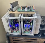
I did just order three modushop mini dissipante 3RU x 300 cases (yay 20% off summer sale!) so looking forward to getting these things finalized.
Michael
I am totally slacking on my dual 300A2 build. Instead of purchasing the Micro-Audio PSUs (which I still intend to do), I dropped the funds on a pair of JBL 580s.So did you get everything together with the extra caps and opposite polarity like suggested in that white paper you linked to? Curious to know if it made a difference. Although it didn't look to be a huge problem to begin with, getting rid of it all together is probably a good thing seeing how it can be destructive.
So how goes your build Andrew?
From what I can gather, even if I am going to use the two 300A2s in BTL (each driving a single channel), I should error on the side of caution and pick up two PCBs and the appropriate caps to minimize bus pumping?
From what I've read on the subject, which wasn't a whole lot but what I did gather was that this is an issue with single ended outputs and not BTL. So you shouldn't need any of that.I am totally slacking on my dual 300A2 build. Instead of purchasing the Micro-Audio PSUs (which I still intend to do), I dropped the funds on a pair of JBL 580s.
From what I can gather, even if I am going to use the two 300A2s in BTL (each driving a single channel), I should error on the side of caution and pick up two PCBs and the appropriate caps to minimize bus pumping?
From what I've read on the subject, which wasn't a whole lot but what I did gather was that this is an issue with single ended outputs and not BTL. So you shouldn't need any of that.
I haven't tested BTL (yet) but it would seem that would be the only configuration where you can truly count on identical input signals so it might not be much of a concern. I plan on using two amplifier modules in BTL mode but decided to add the extra capacitors so that I could have 3 identical 4 channel amplifiers.
When I have a second I'll setup a module in BTL without the extra capacitors board and run the same frequency sweep measurement to see what it looks like.
Michael
Those of you using 300A2, are you using balanced or unbalanced input?
I just noticed in the manual they suggest tying IN(-) to ground for what they call ‘semi balanced‘ input.
The cable set I got from Ghent has +/-/shield for the input cable. I only connected + and - on my chassis RCA input. Should I solder the shield to the negative connector?
I just noticed in the manual they suggest tying IN(-) to ground for what they call ‘semi balanced‘ input.
The cable set I got from Ghent has +/-/shield for the input cable. I only connected + and - on my chassis RCA input. Should I solder the shield to the negative connector?
Attachments
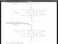
If your cables are shielded only connect the shield at the RCA's. Connect it to the - but leave it disconnected at the board. You will probably have to rearrange the wires at the connector for "semi balanced".Those of you using 300A2, are you using balanced or unbalanced input?
I just noticed in the manual they suggest tying IN(-) to ground for what they call ‘semi balanced‘ input.
The cable set I got from Ghent has +/-/shield for the input cable. I only connected + and - on my chassis RCA input. Should I solder the shield to the negative connector?
I'm using the semi balanced inputs but I'm using twisted pairs instead of shielded wires so I only have the two wires to worry about. I'm not getting any distortion or RF interference.
Thanks. I currently have it wired backwards from what you suggest: the premade cable shield is connected at the board connector and not connected at the RCAs. I have the faintest hiss and mains hum at my speakers, but it's not noticeable even 6 inches away.
I will open the amp up when I get my meter driver board delivered and switch up the input connections to see if the hiss/hum goes away.
https://www.diyaudio.com/community/threads/class-d-amp-photo-gallery.87913/post-7074424
I will open the amp up when I get my meter driver board delivered and switch up the input connections to see if the hiss/hum goes away.
https://www.diyaudio.com/community/threads/class-d-amp-photo-gallery.87913/post-7074424
If it's working then I wouldn't worry about it. It can be hooked up either way as long as the shield is only attached at one end you should be good to go. So are you using passive cross overs or are you using active/DSP?Thanks. I currently have it wired backwards from what you suggest: the premade cable shield is connected at the board connector and not connected at the RCAs. I have the faintest hiss and mains hum at my speakers, but it's not noticeable even 6 inches away.
I will open the amp up when I get my meter driver board delivered and switch up the input connections to see if the hiss/hum goes away.
https://www.diyaudio.com/community/threads/class-d-amp-photo-gallery.87913/post-7074424
So I take it you are happy with micro audio? It's good to see some people using these icepower amp modules. They really do sound amazing.
Just passive crossovers for me. One module, single ended stereo. I agree, the amp sounds very very good.
MicroAudio SMPS are just great. I have nothing but praise for their products and exceptional customer service.
MicroAudio SMPS are just great. I have nothing but praise for their products and exceptional customer service.
Cool I saw your build on the thread you linked. Looks good. The VU meters where lit up. Do they work?Just passive crossovers for me. One module, single ended stereo. I agree, the amp sounds very very good.
MicroAudio SMPS are just great. I have nothing but praise for their products and exceptional customer service.
Thanks! I am waiting on some meter driver boards from eBay. They will be operational soon!Cool I saw your build on the thread you linked. Looks good. The VU meters where lit up. Do they work?
Do you need driver boards to drive them? I was under the impression that you hook them straight to VMon1 and VMon2 with reference to ground.Thanks! I am waiting on some meter driver boards from eBay. They will be operational soon!
Well that’s interesting… I didn’t realize that about the 300A2 boards. I will try that, but I think I would be exceptionally lucky if that worked with the old meters from the chassis.
I tried Vmon 1 and 2 wired to the meters and used the SMPS aux 12v for the lamps, but the needles barely moved, even at full output. I wired up the meter driver board and got them to move appropriately, but there was a bad mains hum… Oddly I didn’t have mains hum with my iPad as the source at the testing phase. I’ll have to investigate further. It’s possible my kluged crimp connectors on the meters and spliced wires are inadequate/faulty. If the board doesn’t work out, I’ll wire up a simple circuit like I did for another amp with meters.
The good news is I swapped out the 300A2 amp in my main system with a build I haven’t used in a while (TubSuMo monoblocks), and it sounds fantastic, too. 🤓
The good news is I swapped out the 300A2 amp in my main system with a build I haven’t used in a while (TubSuMo monoblocks), and it sounds fantastic, too. 🤓
Attachments
Those are interesting mono blocks. What's the wattage on those? So it uses a tube pre-amp?I tried Vmon 1 and 2 wired to the meters and used the SMPS aux 12v for the lamps, but the needles barely moved, even at full output. I wired up the meter driver board and got them to move appropriately, but there was a bad mains hum… Oddly I didn’t have mains hum with my iPad as the source at the testing phase. I’ll have to investigate further. It’s possible my kluged crimp connectors on the meters and spliced wires are inadequate/faulty. If the board doesn’t work out, I’ll wire up a simple circuit like I did for another amp with meters.
The good news is I swapped out the 300A2 amp in my main system with a build I haven’t used in a while (TubSuMo monoblocks), and it sounds fantastic, too. 🤓
I kind of wanted VU meters on my build but it would have been way to much work cutting out the front plate for 6 meters and it would have cost a small fortune just to buy the meters so I opted out. Plus my amp is for powering a set of 3 way active speakers and wouldn't really mean much in that regard. Maybe if they monitored the stereo input they would be better. What does that driver board look like? Can it be used to drive meters from the low level input side as opposed to the output side? Do you have a link to it?
- Home
- Amplifiers
- Class D
- Why do i have 56v on my vdrive?