that looks similar to a sim ive done for my current 2ways, using the al130 and g20sc, almost identical. The electrical slmpe is 2nd order, but acoustic slope is not.
Phase tracking SHOULD be this good, after all boxsim optimises it very well for you 😀, UNFORTUNATELY, whilst the g20sc is certainly has a flat response, theres something i have grown to dislike about its low end sound. Maybe its the sound of domes at 1-3 k that ive come to dislike,
Phase tracking SHOULD be this good, after all boxsim optimises it very well for you 😀, UNFORTUNATELY, whilst the g20sc is certainly has a flat response, theres something i have grown to dislike about its low end sound. Maybe its the sound of domes at 1-3 k that ive come to dislike,
Last edited:
Very nice
I can do better! This uses a crossover 1uF/6.2 ohm TANK on the bafflestep coil. That rolls of the bass sharply with a notch around 5kHz:
An externally hosted image should be here but it was not working when we last tested it.
It happens to do lovely things to phase too:
An externally hosted image should be here but it was not working when we last tested it.
Frequency response looks good too, albeit impedance drops a bit at the very top:
An externally hosted image should be here but it was not working when we last tested it.
Sadly I don't know enough about my own woofer to implement this, but a useful technique, eh?
Electrically it is very pleasing to me. Is it possible a large population size has converged on a design similar to this one. Gen, lets hear about that acoustic slope 4th order ?
What about that magical crossover point ? 2 way or 3 way which wins the day ?
If the high frequency driver was of another form other than a coil, how would that crossover look ?
How does this fare versus your actives ?
What about that magical crossover point ? 2 way or 3 way which wins the day ?
If the high frequency driver was of another form other than a coil, how would that crossover look ?
How does this fare versus your actives ?
This is just an assumption:
At that crossover point the low end will not sound good. It is still contaminated by high frequency elements, that the ear is sensitive to.
A system that has a crossover at around 300Hz should sound good.
http://upload.wikimedia.org/wikipedia/commons/4/47/Lindos1.svg
At that crossover point the low end will not sound good. It is still contaminated by high frequency elements, that the ear is sensitive to.
A system that has a crossover at around 300Hz should sound good.
http://upload.wikimedia.org/wikipedia/commons/4/47/Lindos1.svg
Last edited:
System7 would you kindly indulge us with a listening experiment where you have a crossover point at 300Hz ?
the acoustic slope is somewhere between 3rd and 4th, cant post plot as im on my mobile lol. @ system7, to deal with the al130 peak i didnt use a tank tho, instead preferring to just add inductor in series with the lp shunting cap. Just as effective re phase and fr, but small value L, ie no extra series cap. Imo a better idea, tho someone else may need to confirm this.
I used to have these monstrous huge bextrene Chartwell PM400 monitors, so I know how low crossover can work very well!
Just happen to be more interested in smallish 2-way bookshelves these days. 😀
@Mondo, no particular feeling about tanks, think I prefer traps and Zobels in fact. But if you are brave enough to take on metal cones, you're going to need some strong medicine to get them listenable!
My own observation is that some drivers are just plain nicer to work with. Some of Visaton's bass units are a bit difficult, but the 0.6mH W130S seems rather good with a trap. I only use the GC20 to model because it's a typical ferrofluid dome design. I'm guessing with my own drivers. 😱
An externally hosted image should be here but it was not working when we last tested it.
Just happen to be more interested in smallish 2-way bookshelves these days. 😀
@Mondo, no particular feeling about tanks, think I prefer traps and Zobels in fact. But if you are brave enough to take on metal cones, you're going to need some strong medicine to get them listenable!
My own observation is that some drivers are just plain nicer to work with. Some of Visaton's bass units are a bit difficult, but the 0.6mH W130S seems rather good with a trap. I only use the GC20 to model because it's a typical ferrofluid dome design. I'm guessing with my own drivers. 😱
Thanks system7. For curiosities sake 😀
1. Do you have a driver that can do between 20k to 300Hz ?
2. If yes substitute the high frequency driver on your bookshelves with it
3. Move crossover point to 300Hz
Cheers
1. Do you have a driver that can do between 20k to 300Hz ?
2. If yes substitute the high frequency driver on your bookshelves with it
3. Move crossover point to 300Hz
Cheers
hate to say it system7 but your crossover is almost identical to mine lol. The metal cone res is down some 50db in my sim...the passband is the flatest ive seen for a long long time, w170 are nice, but relatively for paper, the breakup is rough. Try the same circuit with the al130, 2.2mH with 5uf. Hp goes from .27 to . 33. Almost identical as i said. In the scheme of things al cone is no worse than bextrene, both rigid cones, same issues to deal with. Take my word, or if u cant, then try.
But is it correct to call it a L/R alignment (as many people do) if its constructed of asymmetric slopes, one of which is potentially an odd order, and a (driver position) time delay is involved as well ?Its true that theoretical LR filters (acoustical or electrical) will be cascades of identical Butterworth and therefore of even order, but in practice you can create "in phase" networks with even or odd combinations. Since interunit driver delay is arbitrary you can choose whatever filter order that gets phases to overlap, adjust to have -6dB at the crossover point, and achieve response as flat as you could want. It can be near perfect in practice even if not perfect in theory.
If it sums to 0dB (-6dB each section at the crossover point) and tracks approximately in phase through the crossover region, is that enough to actually call it a L/R alignment, or is it merely a phase tracking crossover that somewhat approximates a L/R response but isn't one ?
Isn't one of the characteristics of a L/R alignment that the phase of the two sections tracks perfectly at all frequencies, not just through the overlap region ? If so wouldn't an asymmetric slope and/or a driver time delay fail to meet this requirement ? (Perhaps of academic interest in speakers, where phase tracking outside the overlap region is a moot point)
I have a 3rd order 4Khz crossover that with a small driver offset (about 20mm) that ends up tracking in phase over 2 octaves and summing flat but I would hesitate to call that a L/R crossover...
Perhaps I'm being a bit pedantic about the definition, but certain filter alignments like butterworth, L/R etc have very specific attributes that define them, so something that "looks a bit like" one of them still isn't one, even though it could approximate some of the criteria.
Yes good point. So what would the two Q's be of a 4th order L/R - both 0.707, since its made of two cascaded 2nd order butterworth ? Unlike a 4th order butterworth where the 2 Q's are different.With regard to "Q of 0.7", lets not forget that 0.7 is the Butterworth Q for second order only. All other orders will have a range of Q's ranging from higher to lower. This is a commonly repeated error because we so frequently discuss second order filters.
Another way to think about Q conceptually is that its the rate of energy loss that occurs in a resonator as the energy exchanges back and forth between (in the case of an electrical resonator) a coil and a capacitor. And another way of thinking about a 2nd order high pass or low pass filter is that it is actually a tapped series tuned resonator...
If theres only one coil or a capacitor there can't be a Q because there is no resonator formed, thus no stored energy to decay, and if you have a 4th order filter you have two tapped resonators which each must have their own Q depending on their internal losses and external loading.
Last edited:
Yes I shouldn't have said stored energy as its not technically correct to use it to mean only resonances, although thats often what is often done in audio...simon: a single coil or cap is still a reactive element, and will store energy,
I'll give you a coil and a resistor, (or a cap and a resistor) show me how any "resonance magnification" (such as response peaking) occurs under any circumstances. It's impossible to get any resonance when only one reactive component is present. I presume they covered that in EEEng as well 😀and induce voltage or current magnification depending on series or shunt placement.caps discharge and coils mag field collapse, hence they will still have a resonance magnification, ie Q
im certain this is what i learned during EEEng degree...
In some ways the roll off slope of a 1st order filter can be thought to have a Q of 0.5, (critically damped) but I'm not sure that it's technically correct to treat it as a Q value at all, and you certainly can't manipulate the "Q" value of a 1st order filter. It is what it is. If you change the load resistance you just change the cutoff frequency.
But is it correct to call it a L/R alignment (as many people do) if its constructed of asymmetric slopes, one of which is potentially an odd order, and a (driver position) time delay is involved as well ?
If it sums to 0dB (-6dB each section at the crossover point) and tracks approximately in phase through the crossover region, is that enough to actually call it a L/R alignment, or is it merely a phase tracking crossover that somewhat approximates a L/R response but isn't one ?
Isn't one of the characteristics of a L/R alignment that the phase of the two sections tracks perfectly at all frequencies, not just through the overlap region ? If so wouldn't an asymmetric slope and/or a driver time delay fail to meet this requirement ? (Perhaps of academic interest in speakers, where phase tracking outside the overlap region is a moot point).
Call it "L/R like" or simply "in phase crossovers". All the theoretical papers on crossovers come at it from an ideal model, usually adding electrical networks or transfer functions to reveal a model of how multiway loudspeaker sections may add.
The L/R paper simply adds together a highpass and a lowpass and does have phase overlap for all frequencies. Even an ideal model would deviate from that if it was more realistically modeled as summed bandpasses. The LF corner of the woofer and the ultimate roll off of the tweeter would cause phase divergence away from the crossover point. No matter, we can only hope to get decent tracking over the crossover region and don't care in practical terms, once either unit is 20-30 dB down.
The practical in-phase crossover system give us everything we want: flat response and freedom from asymmetrical polar issues. The L/R paper doesn't constrain us to the only solutions.
David
You probably mean series LC.simon: first order bandpass..? That has Q...due to series RC
It can have Q above 0.5 (complex pole pairs rather than real) but it depends on the values of the L and C. As soon as the highpass corner is lower than the lowpass corner it becomes two separate first orders.
David
yes simon, i realised my error and tried to correct myself before the resultant flaming lol.
To the best of my knowledge, or error it would seem today, 1st order is by its very nature, always critically damped, maybe the 0.5 Q is due to the other formula for calculating Q? My brain has taken a flight to the other side of the globe, or id quote it, and test whether it is the case, im only guessing here.
And yes dave i meant LC, Soz for my absent mind...its been one of those weeks
Last edited:
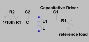
I haven't figured it out. Electrostatics can be treated as capacitors.If the high frequency driver was of another form other than a coil, how would that crossover look ?
I work from this observation these days:
An externally hosted image should be here but it was not working when we last tested it.
When you use voicecoil inductance Le and twice Zobel capacitance in the low pass, it seems to work out VERY nicely. This is going with the natural rolloff of a drive unit, rather than fighting it.
http://www.diyaudio.com/forums/multi-way/212926-what-makes-sound-stick-speakers-8.html#post3032880
A third order butterworth has a beautiful hexagonal symmetry if you have a geometric point of view of the poles:
An externally hosted image should be here but it was not working when we last tested it.
As far as I've got so far, a fullrange tweeter and a fullrange bass work well together with second order on both shunts. If the tweeter (as most do...) has a natural highpass built in, you need third order on the tweeter to get something that works nicely. Not sure. It's a good question. There's a rightness about even order Linkwitz-Riley and odd order Butterworth that repays further investigation. 🙂
nice technique, seems to depend greatly on having the right Le, rather than a low Le in particular.
Very nice😉
Could look like this passively
But due to loses maybe this is where actives come in
I haven't figured it out. Electrostatics can be treated as capacitors.
Could look like this passively
But due to loses maybe this is where actives come in
Attachments
Last edited:
Very nice😉
Could look like this passively
But due to loses maybe this is where actives come in
I would imagine you can treat it much like a Piezo-electric tweeter, and shunt it with a resistor say 8 Ohms, or 16 Ohms for (perhaps) convenience. then design crossover as a ~ 8 Ohm load, or more exactly, like a Parallel RC network. Potentially high Capacitance might be an issue...Im not 100% sure....Maybe that an avenue worth persuing?
Maybe something like this...im not 100%

Series cap for protection only,may want to add a series R instead. Though it may not be needed at all, the trap may be enough.
*aside: Isnt the Q=0.5 thing something to do with Half Power, rather than amplitude?
Last edited:
- Status
- Not open for further replies.
- Home
- Loudspeakers
- Multi-Way
- Why 2nd Order Is best or not