Re: Class D has been revived in popularity
We might consider asking the website owner to make a "diyAudio Forums > Top > Amplifiers > Class D" entry. After all, it is sufficiently different from "normal" solid state amplifier to merit its own subdivision.subwo1 said:I think it is good that you appeared here, because interest in class D was waning.
The bottom half of the comparator can be equipped with a second pair of output transistors to drive a second half bridge. I am wondering, however, what would be the best "everyman's diy class D power stage". One using gate driver ICs or a fully discrete one? Both come with their own set of problems. Of course, the only really problem-free solution is to buy a module from Jan-Peter. 🙂subwo1 said:(...) so that is a mandate for bridging (...)
The bottom half of the comparator can be equipped with a second pair of output transistors to drive a second half bridge. I am wondering, however, what would be the best "everyman's diy class D power stage". One using gate driver ICs or a fully discrete one? Both come with their own set of problems.
I think the main issue here is to have a good PCB layout. Soldering everyting together is an easy task afterwards, as long as the circuit doesn't need too much adjustment. Also the component choice should be reasonable (not too many exotic semiconductors, inductor cores made out of unobtainium, etc etc).
Regards
Charles
I second that notion.We might consider asking the website owner to make a "diyAudio Forums > Top > Amplifiers > Class D" entry. After all, it is sufficiently different from "normal" solid state amplifier to merit its own subdivision.

Being somewhat adverse to physical labor, I would go for pre-made modules or IC chips if the conditions of price, power, and performance were right. That presently prototyped Hypex 400w version is one I may like to check out....the only really problem-free solution is to buy a module from Jan-Peter. 🙂
I had considered only the former option until recently because gate drivers can supply much greater peak current. I have gotten capacitive coupling to the mosfet drivers to work in simulation so that propagation delay is minimized. But, then, the discrete component method is simpler, though maybe less efficient and more problematic for high output power.The bottom half of the comparator can be equipped with a second pair of output transistors to drive a second half bridge. I am wondering, however, what would be the best "everyman's diy class D power stage". One using gate driver ICs or a fully discrete one?
Hi Jan-Peter,
where i can see specs of your UcD boards, and when this boards will available? Something about price?
where i can see specs of your UcD boards, and when this boards will available? Something about price?
Hi Ivan,
The specs of the board will be comparable with the original Philips IP Board, http://www.hypex.nl/classd/classd.PDF
On our website, www.hypex.nl, we will present the first model next week with some photos and price.
I don't want to use the forum for really commercial advertisment, altough it is hardly avoidable when we talk about UcD 😉
Regards,
Jan-Peter
www.hypex.nl
Bruno,
I'm wondered, it isn't optimal loop system or something other? Accidentally i've noticed the reducing of THD at 1.5-2 times (of course sw.freq. reduced also) by hands touching between +input and output (after filter). Using 27pf and 47kohm(potentiometer) gives possibility to find of the THD minimum, but adjusting is fine(unstable) too much (i saw 0.004%@5khz 24khz bandwidth, about 330khz sw.freq., DC gain are 23db). Without this trick the THD biger at the same sw. frequency...
Jan-Peter,
presentation next week?
IVX said:Bruno,
Using 27pf and 47kohm(potentiometer) gives possibility to find of the THD minimum, but adjusting is fine(unstable) too much (i saw 0.004%@5khz 24khz bandwidth, about 330khz sw.freq., DC gain are 23db). Without this trick the THD biger at the same sw. frequency...
The modulationitself is not inherently linear. It produces some distortion products itself. At certain power levels it happens that the third harmonic of the modulation exactly cancel those of the power stage. At 5kHz you're most likely measuring the 3rd harmonic only. If you perform a THD vs power sweep at 5kHz you'll find that nearly every loop setting has a spectacular THD dip at some power level between -6 and -3dB.
Since the loop gain is constant over the audio range, you can equally well measure at 1kHz. This includes enough harmonics in the measurement to get a more complete picture.
Hi Bruno,
once I speculated how your multiphase DSD amplifier might work.
"My idea on how to do it on raw sigma delta data stream (let's say this is 2.8MHz DSD) is as follows:you take 8 consecutive data samples from N to N+7 and count number of ones in it. At N+8 you output another 8 cycles long data stream which now has all the counted ones at the beginning and the remaining zeros at the end. At the same time you count ones in another sequence of input data stream from N+8 to N+15 and then output counted ones first. So basically input DSD data stream is transformed into 2.8MHz/8 PWM modulated data stream with 8 level resolution. Now if you take the same algorithm, but process input data from N+1 to N+8, you get another PWM modulated data stream, but this time phase shifted 12.5%. If you again repeat this with another input data set from N+2 to N+9 and so on you eventually have 8 phase shifted PWM modulated data streams, each with 350kHz switching frequency. But the resulting switching frequency after summation is again 2.8MHz not counting ripple current cancellation. This results in almost negligible current ripple at the output. One can also use one transistor and diode (as in Crown BCA) instead of half bridge for each PWM output stage thus reducing complexity. I really don't know how the noise spectra of such manipulation would be, but I hope it would not be worse than before."
Do you think it may work?
Best regards,
Jaka Racman
Jaka Racman said:once I speculated how your multiphase DSD amplifier might work.
(...snip...)
Do you think it may work?
Speculated? I wrote an AES paper about how it works. It was presented in 2002 (AES112). Those who are curious should provide me with their email address and I'll send it.
The modulation scheme you present is not invariant. The summed output of the eight switching legs should be a filtered version of the incoming DSD. In the case of PPDSD this is a flat running average (n taps, ie. count ones in the n past samples). If we do the same analysis on your idea, it turns out that the impulse response varies with the actual data content, due to the reshuffling of the bits to form PWM.
A notable demonstration is a signal like
"...0000000000001111111111111111111100000000000...".
In PPDSD, this comes out as
"...0000000000001234567888888888888876543210000...". This shows the impulse response is a square of 8 ones (comb filter). The step response is a linear ramp, as attested by the rising and falling edges of the output train.
Your scheme produces something quite different:
"...0000000000001122334455667788888888888800000..."
Rising and falling edges are different! This amounts to a signal-dependent variable delay. This invalidates the sampling domain and demodulates the HF noise.
Close but no cigar 🙁
Cheers,
Bruno
Hi Bruno,
I was not aware of your paper, but I would like to read it.
Best regards,
j.racman@email.si
I was not aware of your paper, but I would like to read it.
Best regards,
j.racman@email.si
Hi All,
I had promised a presentation of the DIY Class-D module on our website. Unforternatly we are quit busy with upgrading a 2-way and 3-way analog amplifier for one of our OEM customers to UcD, so less time for upgrading our website.
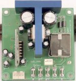
But hereby a photo of our 180W DIY UcD Class-D module!
Regards,
Jan-Peter
www.hypex.nl
I had promised a presentation of the DIY Class-D module on our website. Unforternatly we are quit busy with upgrading a 2-way and 3-way analog amplifier for one of our OEM customers to UcD, so less time for upgrading our website.
But hereby a photo of our 180W DIY UcD Class-D module!
Regards,
Jan-Peter
www.hypex.nl
Attachments
Hi Jan-Peter
It looks cool, to say the least.
It makes the impression as if it would use a dedicated IC, containing everything but the output stage, doesn't it ?
How much will it cost approximately ?
Regards
Charles
It looks cool, to say the least.
It makes the impression as if it would use a dedicated IC, containing everything but the output stage, doesn't it ?
How much will it cost approximately ?
Regards
Charles
Hi Charles,
Thanks for your nice comments.
A Class-D amplifier should always look `Cool`.....;-)
No, no....... no dedicated IC. All is SMD transistors, and full discrete. The only IC is an input gain opamp to increase the gain to 26dB. Currently I have used a NE5532 probably we move to a OPA2134.
This version will be with High graded Audiophile components.
Some specs:
Power 8 Ohm - 100W.
Power 4 Ohm - 180W.
Outputimpedance - 0,010 - 0,020 Ohm.
Flatfrequency responce undependend from load.
THD - 0,005% - 0,05%, 0,1W - 80W at 8 Ohm load.
Switchingfrequency - +/- 400kHz.
Easy mounting.
Only 2 voltages, +45VDC and -45VDC.
Shortcircuit protection.
Power supply pumping protection.
All Audiophile components.
Cool Blue looking, blue anodized aluminium and blue amp on LED.
Etc.....
Price one module €60,00 ex. VAT, ex. shipping.
We are currently busy with a 400W version.
Regards,
Jan-Peter
www.hypex.nl
Thanks Jan-Peter,
the dimension seems about 65x65? Can i ask you about filter coil type (vendor, core material, gap)?
edited: confidential? Ok, thx anyway.
the dimension seems about 65x65? Can i ask you about filter coil type (vendor, core material, gap)?
edited: confidential? Ok, thx anyway.
Ivan,
Indeed size is 65 x 65mm.
Core is EP17 suitable for 400kHz.
The rest of the information is confidential, I am sorry.
Jan-Peter
www.hypex.nl
Indeed size is 65 x 65mm.
Core is EP17 suitable for 400kHz.
The rest of the information is confidential, I am sorry.
Jan-Peter
www.hypex.nl
It wouldn't make much sense to give the detailed info of the core that's inside JP's chokes. Each ferrite supplier has a selection of grades (types) that don't correspond 1:1 to those of others. In addition, each company uses a different naming system.IVX said:Can i ask you about filter coil type (vendor, core material, gap)?
What I can do is point you in the direction of the information.
Of the European suppliers, both the Ferroxcube and Epcos websites have their data books online. The introduction outlines the basics of how to select cores and how to design chokes. The information is quite complete but not very clearly written. From this (and with a bit of imagination) you can derive all the formulae needed to design a choke from scratch.
There's also a design tool available which delivers very conservative designs. I prefer to do my own calculations because then I understand where the result came from.
The trade-off revolves around peak current capability (=saturation), rms current capability (resistive heating), core size and length of the air gap.
Other stuff to look at which are not mentioned are electrical and magnetic shielding and winding losses caused by proximity effects.
Good luck!
Bruno
- Home
- Amplifiers
- Class D
- Which chip and whatever happened to Mueta and UCD?