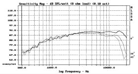
The graphs on Seas datasheets are actual 4pi measurements of driver mounted in a standard cabinet (see attachment) so, if your box volume/size is similar, you have valuable data to input in your simulation program as baffle step is already included.
The dotted line is an approximation of the FR measured on an IEC baffle.
As to Xmax you can use VituixCad panels in the Enclosure tool that gives a lot of info.
Seas CA22RNX in 25L box: the max output level (light blue curve) is reached at 20W

Cone excursion at 20W is below Xmax so you are fine.

The dotted line is an approximation of the FR measured on an IEC baffle.
As to Xmax you can use VituixCad panels in the Enclosure tool that gives a lot of info.
Seas CA22RNX in 25L box: the max output level (light blue curve) is reached at 20W
Cone excursion at 20W is below Xmax so you are fine.
Attachments
Thanks for that. I had noticed that VituixCad offers a lot of facilities but 😉 the shear number of them left me wondering if I could use it. I had noticed it can be run under Linux and there are decent instructions for installing it.
🙂 I'm learning. Boxsim has been pretty useful for that with help from it's optimiser and then tinkering with values. The optimiser has various sliders to weight some aspect but always chases phase. It can be difficult to get xover F's where they could be. The designs database has a lot of variations in it. All helps.
As I haven't done a notch filter I am going to see if I can push the xover F up on a W170s. It has a peak at about 5k. Referenced to 8ohms I can see that I could use 20w at 30Hz. Also that I would have grief at 40. Spl at 40hz 95. Below these problems - some suggest add a filter. I can look at that but have doubts if that is viable with LC circuits. Above 100Hz > 100dB spl.
🙂 When it comes down to woodwork warmer weather would be a good idea. I could do it in the house but the room is now more of a store room so rather hard to clean up.
Also stuck with an AV receiver, It most;y decides what to do via a mic. Maybe it's time to look for another that like TV's has it's auto facilities but also set things as wanted if some one wants.
Don't get too hung up about flat FR.
Just because you can hammer the FR into a flat curve doesn't mean it will sound good. Some drivers just don't sound good at various xover points / slopes despite the distortion measurements. Its more important to get the timing right in the mids without large, sudden phase shifts. This implies getting rid of any resonant peaks, even if they're 20+ dB or so down in the xover rolloff. These ugly peaks are what ruin the overall transparency in the mids. Always suppress them and also verify their dealt with using your ears. Sometimes you can still hear them even though measurements indicate otherwise.
Usually you'd pick your midbass or midrange driver first. That's really where most of the performance is. The treble is in most cases much easier to deal with and there are far less perceived differences in most dome tweeters than cone drivers.
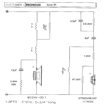
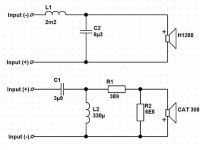
By sheer persistence in going through all the relevant threads on DIY Audio I unearthed a crossover for the CA22RNX plus Morel CAT308. This is the closest I have come yet to a crossover I could use. I think xover is 2K? What do you think? I now have a pair of SB26ADC to use. They are 4 ohm, the CAT308 is 8 ohm so some modifications look like they need doing........
https://difton.wixsite.com/difton/diy2
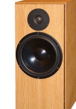
https://difton.wixsite.com/difton/diy2


you will not see how it works w/o benchmark both side to side. Be confident to the knowledge advised but if a self learning process which involve more monney spent for learning purpose (it's a hobby do it is a part of the pleasure)
I think it's 3-4k and the woofer will operate in break-up at that frequency.I think xover is 2K?
In the attached zip file you find the FR and impedance file of the drivers you chose, input in a simulator like vituixcad and play with them.
Attachments
< I think it's 3-4k and the woofer will operate in break-up at that frequency.
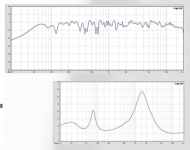
What suggests 3-4K? The impedance curve shows a big peak at 1.5K. I can't see the crossover frequency mentioned in the text, but my Russian is rather basic.... ah, just read the xover is 3K. Also says "filter is of the second order." That's too high. Needs to be 2K. Back to the drawing board.
What suggests 3-4K? The impedance curve shows a big peak at 1.5K. I can't see the crossover frequency mentioned in the text, but my Russian is rather basic.... ah, just read the xover is 3K. Also says "filter is of the second order." That's too high. Needs to be 2K. Back to the drawing board.
Last edited:
The impedance peak in the system's final curve won't be an accurate indicator of actual acoustic xover frequency. Thats what really counts and the electrical response itself isn't the whole story.
Using a non WG tweeter has completely different xover requirements than a direct radiating dome in terms of filter slope, phase behavior, level and EQ needed to get a flat-ish response. You won't be happy with the results if you just copy the HP filter of one design, combined with the LP of another. Thats a complete waste of time, other than just for experimental purposes.
You'll need to cross the CA22RNX around 2k in a 2 way, otherwise you'll have weird off axis behavior, power response and beaming, plus running the woofer in breakup as explained above. That amounts to a waste of good parts due to a lack of proper xover for the specific drivers. You won't be happy with the results. I can guarantee you that.
I hear all your misgivings, but the plain fact is I need some sort of crossover to start with just to get sound. No waveguide in the SEAS Trym design and crossover is 1.6K so we are in the ballpark at least. Different drivers beyond my budget but it could be a point of departure. I haven't yet found any crossover that crosses the CA22RNX around 2K so I'm waiting to buy a mid-bass until I have a crossover in mind. I need at least something pretty close.
https://www.seas.no/index.php?optio...id=384:trym-seas-diy-kits&catid=66&Itemid=250
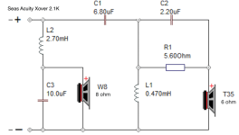
There's also the SEAS Acuity, another 8+1 with a crossover at 2.1K
https://www.seas.no/index.php?optio...-acuity-kit&catid=66:seas-diy-kits&Itemid=345
https://www.seas.no/index.php?optio...id=384:trym-seas-diy-kits&catid=66&Itemid=250
There's also the SEAS Acuity, another 8+1 with a crossover at 2.1K
https://www.seas.no/index.php?optio...-acuity-kit&catid=66:seas-diy-kits&Itemid=345
Are you settled on a 2 way with the CA22 and SB26ADC (without waveguide)? I can give you a passive crossover simulation (assuming you're going passive) if you're willing to wait a week or so. What I need are:
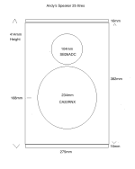
1. baffle dimensions
2. Whether the edges are rounded or squared or chamfered / faceted
3. driver placement on baffle for each driver
4. enclosure volume and (if vented) tuning (Fb / port size / length if vented)
5. How much baffle step compensation you want (I'll go for ~4dB if no preference)
1. baffle dimensions
2. Whether the edges are rounded or squared or chamfered / faceted
3. driver placement on baffle for each driver
4. enclosure volume and (if vented) tuning (Fb / port size / length if vented)
5. How much baffle step compensation you want (I'll go for ~4dB if no preference)
There's also the W22NY plus 27TBCD 8+1 with a crossover at 2K
https://www.madisound.com/library/stacks/LEAP-W22NY-001-H1499.pdf
And as mentioned before the chefsinc crossover for the SB23NRX, though this was done by ear and has various mods...

https://www.madisound.com/library/stacks/LEAP-W22NY-001-H1499.pdf
And as mentioned before the chefsinc crossover for the SB23NRX, though this was done by ear and has various mods...

Thanks Dave, that would be great. I'll scare up some drawings for you.Are you settled on a 2 way with the CA22 and SB26ADC (without waveguide)? I can give you a passive crossover simulation (assuming you're going passive) if you're willing to wait a week or so. What I need are:
1. baffle dimensions
2. Whether the edges are rounded or squared or chamfered / faceted
3. driver placement on baffle for each driver
4. enclosure volume and (if vented) tuning (Fb / port size / length if vented)
5. How much baffle step compensation you want (I'll go for ~4dB if no preference)
I see crossovers with mediocre baffle step compensation all over the place. Big series coils that excessively reduce level below the baffle step. Calculate the impedance of a 2m2 coil plus 1m inductance of the voice coil at 500Hz and you know what I mean.
< I see crossovers with mediocre baffle step compensation all over the place. Big series coils that excessively reduce level below the baffle step.
What's the alternative? Thanks.
What's the alternative? Thanks.
Tricky for a beginner. For instance I am using 1.5mH for an xover of 2.5k. That's how things turned out. There doesn't seem to be any guidance around on what's likely to be achievable.Calculate the impedance of a 2m2 coil plus 1m inductance of the voice coil at 500Hz and you know what I mean.
The simulation tells me it needs a resistance of 300u ohms - probably dissipation related.
Last edited:
- Home
- Loudspeakers
- Multi-Way
- Which 6.5" mid-bass for a sealed box?
