Mach_Y
I looked at your parts list, may give you some suggestions:
For 300B, I have tried Valve Art, Svetlana, JJ Electronics and the
expensive VV300B, I have all of these except the Valve Art in which I already sold, I feel that the best tube for this amp is the JJ Electronics.
Regular metal film resistors from digikey for the 6AN4 cathode is good enough. You do not need premium resistor here.
10000uf/16v beyslag from digikey for the filament is good enough here.
For the 300B filament heater, Schottky diodes from digikey is better than IXY's hexfreds. Actually, regular 4A/50v bridge is good enough here.
Regular metal film resistors from digikey for the bleeders are good enough, no need for premium resistors here.
On the power supply 100uf cap, you do not need dual here, a single is all you need.
This suggestion, I think you should consider. While playing around with my amp, if you are going to use tube rectification, I think you should get a power transformer that has 575v-0-575v at 250ma rating. This is to be sure that you can get past 700v, the transformer from the original schematic where actually for a power supply using solid state diodes. Tube rectifiers has more voltage drop and will therefore drop the B+ below 700V. This suggestion I actually got from Jack Elliano. Another thing is that the schematic from his website, is NOT actually the original schematic, that schematic was done by Chris Beck, Jack Elliano's original schematic were published in Vacuum Tube Valley and is using solid state rectifier diodes.
About the program I used for the schematic, well, I used autocad, not really good for schematic drawing.
As for the ammeter, you connect it at the 300B cathode. Between the cathode and the big adjustable resistor. The current flowing through the cathode is the current you want to monitor. For a voltmeter, you connect it across the 300B Plate and Cathode.
As for the Hammer Dynamics, I built this speaker about 2 years ago, the mods I made with it so far is quite extensive, following the suggestions of people from the single driver website. The mods I made so far are: redesigned crossover, from 12db to 6db, replaced crossover components with premium parts like alpha-core inductors and Hovland caps. Replaced tweeter with Fostex 17H, now I really like the way it sounds, just perfect for me. One thing though, is that this speaker is Big, much bigger than the Cicadas.
Alex Deveza
Mach_Y,
About the resistor across the caps, well, you know, I do not know it came with the caps actually, and its really a bleeder resistor, you really do not need this resistor, the caps will bleed naturally through the bleeders from the power supply resistors. Those resistor at the power supply caps are actually dual purpose, they are bleeder but mainly balancing resistors, they are to insure that the voltage arcross those caps in series are equal.
About your ammeter, if you are going to use my schematic that uses rheostat, then yes you are right, you take the 10ohm resistor out and insert your ammeter. That is actually the resistor I used in measuring the current, so if you have an ammeter, then you do not need them.
Alex Deveza
cdeveza said:Mach_Y
I looked at your parts list, may give you some suggestions:
For 300B, I have tried Valve Art, Svetlana, JJ Electronics and the
expensive VV300B, I have all of these except the Valve Art in which I already sold, I feel that the best tube for this amp is the JJ Electronics.
Regular metal film resistors from digikey for the 6AN4 cathode is good enough. You do not need premium resistor here.
10000uf/16v beyslag from digikey for the filament is good enough here.
For the 300B filament heater, Schottky diodes from digikey is better than IXY's hexfreds. Actually, regular 4A/50v bridge is good enough here.
Regular metal film resistors from digikey for the bleeders are good enough, no need for premium resistors here.
On the power supply 100uf cap, you do not need dual here, a single is all you need.
This suggestion, I think you should consider. While playing around with my amp, if you are going to use tube rectification, I think you should get a power transformer that has 575v-0-575v at 250ma rating. This is to be sure that you can get past 700v, the transformer from the original schematic where actually for a power supply using solid state diodes. Tube rectifiers has more voltage drop and will therefore drop the B+ below 700V. This suggestion I actually got from Jack Elliano. Another thing is that the schematic from his website, is NOT actually the original schematic, that schematic was done by Chris Beck, Jack Elliano's original schematic were published in Vacuum Tube Valley and is using solid state rectifier diodes.
About the program I used for the schematic, well, I used autocad, not really good for schematic drawing.
As for the ammeter, you connect it at the 300B cathode. Between the cathode and the big adjustable resistor. The current flowing through the cathode is the current you want to monitor. For a voltmeter, you connect it across the 300B Plate and Cathode.
As for the Hammer Dynamics, I built this speaker about 2 years ago, the mods I made with it so far is quite extensive, following the suggestions of people from the single driver website. The mods I made so far are: redesigned crossover, from 12db to 6db, replaced crossover components with premium parts like alpha-core inductors and Hovland caps. Replaced tweeter with Fostex 17H, now I really like the way it sounds, just perfect for me. One thing though, is that this speaker is Big, much bigger than the Cicadas.
Alex Deveza
Alex,
Hmm.... plenty to think about there. Ok, even the premium resistors at these quantities are not a big difference in price.. only a couple dollars, so I'll just stick with the better ones for piece of mind 🙂 On the 100uF power supply cap, for the extra couple dollars for the dual unit I'll go with that... not a big deal there. Do I need the dual 470's though??
For the the B+ voltage, do you recommend tube rectification over solid state? Its no problem to increase to 575-0-575 @ 250ma, but am I gaining anything by using tubes here instead of something else? Also, which Shottky diodes do you recommend for the 300b heater filaments... too many in the catalog for me to decide 🙁
I'm pretty much decided on the 100mA meter in place of the 10ohm resistor... with a switch I can just bypass it too. Need to look for a similiar style (round) volt meter too. Possibly a switch to be able to check both the 300b and the driver tube voltage.... hmmm...
Also, for the first resistor on the 300b heater, I thought to use a 10ohm, 25 watt (25 watt rating was the cheapest) rheostat to regulate the voltage to 5 volts. Same thing on the B+ with the first resistor... but a 50ohm 25 watt rheostat. On the 6AN4 filaments, are the 2 27ohm resistors required on your schematic? If so, what is their purpose? What about using a solid state regulator for the various heater voltages? ( no flames please... its just a question) Last, on my schematic, I have R8 and R12 with the drains to ground on the rheostats... is this correct, or should I leave them float?
Here is my schematic to date (I think no mistakes so far)....
Attachments
hi Marc_y,
I saw your circuit already.
Is It really use the 6dj8 for the high voltage rectify.
This is the first time I see use thids method to rectify. I think I will
try later.
About the 300b tubes. I can supply the valve art, JJ electro harmonix TJ/Dull music carbon plate, mesh plate & new mesh plate. I like 300b most, But I only use NOS we300B. In my opinion. I like AVVT C37 Mesh plate 300B & TJ/Full music Mesh most. Good Price ratio. The 300B MESH plate, white ceramic, Gold pins.I can only supply in USD 250 per match pair.
cdeveza,
I had some opinion. In my test, use less wire wound resister in
the circuit is best. I agree that not need the permium metal film resisters as your advise but I still advise use military grade metal film because can use in high voltage. As ther Holco resisters. cannot use over 250~300V. Otherwise will cause the spark. The RS will be the same too. So I choose CGW military resisters, it had stable in high voltage & in high tempersature.
In my experience, I will prefer use several large watt mteal film resister parallel use in the 300b or all triode tube use is better.
I always use Lowther speaker to test. Lowther without crossover so its will very sensitive in the high & detail freq.
But i will use several carbon film resisters in the driver part of the amp. this fine turn can added some taste in the sound of the amp.
I had this opinion because I repair many old WE console amp & I find out many we old amp also use this mix use of resisters.
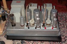
the photo is we k133 amp was use IRC mix AB resisters to use.
thanks for all to give me a chance to share the experience.
Any opinion for my test pls advise.
thanks
Thomas
I saw your circuit already.
Is It really use the 6dj8 for the high voltage rectify.
This is the first time I see use thids method to rectify. I think I will
try later.
About the 300b tubes. I can supply the valve art, JJ electro harmonix TJ/Dull music carbon plate, mesh plate & new mesh plate. I like 300b most, But I only use NOS we300B. In my opinion. I like AVVT C37 Mesh plate 300B & TJ/Full music Mesh most. Good Price ratio. The 300B MESH plate, white ceramic, Gold pins.I can only supply in USD 250 per match pair.
cdeveza,
I had some opinion. In my test, use less wire wound resister in
the circuit is best. I agree that not need the permium metal film resisters as your advise but I still advise use military grade metal film because can use in high voltage. As ther Holco resisters. cannot use over 250~300V. Otherwise will cause the spark. The RS will be the same too. So I choose CGW military resisters, it had stable in high voltage & in high tempersature.
In my experience, I will prefer use several large watt mteal film resister parallel use in the 300b or all triode tube use is better.
I always use Lowther speaker to test. Lowther without crossover so its will very sensitive in the high & detail freq.
But i will use several carbon film resisters in the driver part of the amp. this fine turn can added some taste in the sound of the amp.
I had this opinion because I repair many old WE console amp & I find out many we old amp also use this mix use of resisters.
the photo is we k133 amp was use IRC mix AB resisters to use.
thanks for all to give me a chance to share the experience.
Any opinion for my test pls advise.
thanks
Thomas
Attachments
hi march_y,
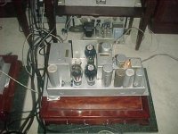
my friend 's we124 amp also use same IRC metal film mix with AB carbon film resisters to use. in the amp.
He use Lowther TP1 & tannoy monitor gold 12 inch, ( I forgot the model no.) But added one Fostex into the Tannoy. Its very good. Still had Horn's density But Added more high air.
Pls see my friend's amp.
thanks
Thomas
Attachments
siu sin man tho said:hi Marc_y,
I saw your circuit already.
Is It really use the 6dj8 for the high voltage rectify.
This is the first time I see use thids method to rectify. I think I will
try later.
About the 300b tubes. I can supply the valve art, JJ electro harmonix TJ/Dull music carbon plate, mesh plate & new mesh plate. I like 300b most, But I only use NOS we300B. In my opinion. I like AVVT C37 Mesh plate 300B & TJ/Full music Mesh most. Good Price ratio. The 300B MESH plate, white ceramic, Gold pins.I can only supply in USD 250 per match pair.
cdeveza,
I had some opinion. In my test, use less wire wound resister in
the circuit is best. I agree that not need the permium metal film resisters as your advise but I still advise use military grade metal film because can use in high voltage. As ther Holco resisters. cannot use over 250~300V. Otherwise will cause the spark. The RS will be the same too. So I choose CGW military resisters, it had stable in high voltage & in high tempersature.
In my experience, I will prefer use several large watt mteal film resister parallel use in the 300b or all triode tube use is better.
I always use Lowther speaker to test. Lowther without crossover so its will very sensitive in the high & detail freq.
But i will use several carbon film resisters in the driver part of the amp. this fine turn can added some taste in the sound of the amp.
I had this opinion because I repair many old WE console amp & I find out many we old amp also use this mix use of resisters.
the photo is we k133 amp was use IRC mix AB resisters to use.
thanks for all to give me a chance to share the experience.
Any opinion for my test pls advise.
thanks
Thomas
That tube is a mistake on my schematic... it should be a 6AU4GTA. None of the ohmite large resistors are wire wound... they are all the wrapped in metal jacket type. Good point on the Holco's or RS resistors. I'll relook those.
Mach_Y,
I will mention the most important first, your r8 and r12 is hooked up wrong. you will definitely have flames(literally), no, to use a rheostat here is to connect the wiper to one of the legs. Again, you do not need a rheostat here, the B+ does not need to be adjusted here, a resistor was placed here to limit the initial current surge somewhat for the rectifier tube, not to control the B+. now for the heater, that resistor is to adjust the voltage. But you will find out that, that rheostat is so big in size and you only adjust it once. On the first amp I built, there was a 0.68ohm/10w resistor in it. Remember, it does not have to be exactly 5volt here, actually I am running mine at around 4.7 to 4.9 volt, better for the tube and no difference in performance, I have tried it with this voltage, exactly 5 volt and around 5.3 volts, and no difference in performance.
On the 6AN4 heater, there is no 27ohm resistor that you mention here. Also, on the first amp I build, there is a 6.8ohm/10w resistor here and we are running the heater at 5.8 - 5.95 volt, again better on the tube.
For the resistors, please read Michaels post, specially the Holcos on the bleeder resistor, low voltage rating. Actually I would not use Holcos on this amp, this amp has lethal voltages, not for Holcos.
Another suggestion on your meter, you can connect it at the plate instead of on the cathode, I think its better at the plate, although, kind of dangerous, its 700+ voltage there, whereas its only 250+ voltage on the cathode, but still lethal though, well, its up to you both will work.
As for solid state vs tube rectification, as I said before, I have build both type and they both sounded good. The first one I built was for a friend of mine and it has solid state rectification, this one was kind of from a kit and have not much flexibility to play around with it, the second one was mine and I used tube rectification, If you ask me, I am a tube guy and all my gear uses tube rectifiers, but thats me. Let me tell you the advantages and disadvantages and I will let you decide for yourself. Tube rectifier have slow turn on, very easy on the tubes, specially the 300B, SS rectifier slams the tubes with high voltages, not good. SS rectifier circuit are cheaper over tubes. On performance, SS have very low forward voltage drop, whereas tube has much larger voltage drop, what this means is that on tube rect, your power supply has higher impedance and the voltage will sag more on demand than the SS counterpart. SS rect can give slightly tigher bass over the tube rect, theoretically, but I have yet to notice this. There are other stuff to consider, but I think these are the important ones.
If you decide to use SS rect, then you should follow the switch arrangement from the first amp I built. It has two switches, one to power the main and the other is to connect the center tap of the pwr tranny to ground. In other words, you turn on the main power first and this will heat up the tube heaters but no B+ yet, then when its pretty heated up, you throw in the second switch to connect the center tap to ground and this will provide B+ to the tubes. This is done to minimize cathode stripping.
BTW, on your schematic, r6 2.5k ohms must be 50w not 25w. I have replaced r4 500 ohms to 250 ohms, I did this to optimize my amp to run at 449v across the tube and 88ma. Also, on the rectifier heater, I have a 0.33/10w on the line, again to limit the voltage a bit below 6.3v.
For the Caps, the first amp I did, had 2 x 100uf/450v and 2 x 220uf/450v, both panasonic from digikey. I increased mine to 470uf/450, because thats what I have on hand and I think the first amp have a bit of hum coming from the ps. Its funny to note that I built my second amp with all recycled parts except for the wooden chassis, I did not buy anything electronic new. Anyway, you can use maybe 330uf or even 270uf, I think 330uf would be good, but I highly recommend using the panasonic from digikey, they are small for one thing and personally, I think they are better than those JJ's or LCR, believe me, I have a bunch of those ELna Cerafines, they are good but the Panasonic are just as good, I myself was very suprised at how they performed, these are the same caps bottlehead are using for their kit. Another thing, because of the nature of this amp, because of its Ultra-Path nature, music does not go through the ps, that is what that big caps are for(hence for No Substitute there), music is short circuited from the B+ to the 300B cathode, it does not go through the PS, so the PS can be any reasonable good caps.
For the Schottky diodes, just look for 4a/16v type and you will be alright, I will see if I can find one for you.
Alex Deveza
Mach_Y,
Sorry when I said read michel post, I meant Thomas, sorry thomas.
Thomas,
I agree on the use of wirewound resistors, but the problem here is that metal film resistors goes only to 1 watt and perhaps 2 watt, this amp uses 50watt resistors, and even then these resistors gets hot. I have to admit, this amp gets very low grade when it comes to efficiency. It dissipates a ton of heat. Also, if you noticed on the schematic, there not much resistors in the signal path to fine tune, its just the cathode resistor on the driver and even that is bypassed by a 100uf/16v cap, that is why I suggest to use Black Gate on this bypass. You will be suprised at how this amp performs that the quality of the sound will mainly depend on the quality of the OPT, the Ultra-Path 40uf/440vac caps.
Alex Deveza
HI cdeveza,
I AGREED THAT this amp need a very large resisters.
So I must use 70pcs 3watt CGW or 10 pcs 2watts dale to parallel to use.
Your questions I think long time already.
About the wire wound large watt. My friend DR. lee was doing another test. His set of Hi
Fi had more detail & expensive than me . He use passive transformer ( silver wire) coupled pre-amp. Also lowther speaker too.
The brand name is
http://www.audio-consulting.ch/
this company made silver wire wound cathode resisters.
Although silver 99.99 pure wire wound but had rich harmonic & high air.
Very expensive But can be the standard for us to test to the other cathode resisters.
He told me that about wire wound, black colour over 7~10 watt black body ohmite & dale is also ok. Use only two to three parallel to use is already.
But there was one brand name use pure Tungsten wire wound large watt resisters.
he said very good. But I must test first. He( DR.Lee) said the the second of the best after the audio consulting & large matal film parallel to use. But he said still Audio. consult & large metal film is the best.
This resisters factory made the platmium resisters ( heat sensor resister) which use in the cyclinder( Fuel conbustion) to detect the temperature. It hadn't any heat noise. Certainly this new testing resister was not the same grade as the heat detect resisters. But they come from same co. I had confident to him.
thanks
Thomas
MOTHER NATURE...
Hi,
Ah...Thomas you found yourself a source that's going to keep you busy for a while.
We've been discussing this here already...at least partially so:
No plastics...all natural insulators and of course silver and gold wires.
No need to pay these prices, most of it you can experiment with yourself, the only expense being your own effort.
Cheers,😉
Hi,
Very expensive But can be the standard for us to test to the other cathode resisters.
Ah...Thomas you found yourself a source that's going to keep you busy for a while.
We've been discussing this here already...at least partially so:
No plastics...all natural insulators and of course silver and gold wires.
No need to pay these prices, most of it you can experiment with yourself, the only expense being your own effort.
Cheers,😉
hi fdegrove,
this is not my experience. Its my friend Dr. lee experience.
That only post to share to other diyers how can solve the wire wound problem that which one will eat less air & high freq.
I am not promote the expensive item. the test is testing about which quite cheap cathode resisters is better. I think many people can effort it. Its only a little more expensive than the metal can dale . I hadn't on hand, its dr.lee 's test & told me.
the resisters also start from 10watt.
thanks
thomas
hi cdeveza,
not need to say sorry.
U welcome.
thanks
Thomas
Sorry when I said read michel post, I meant Thomas, sorry thomas.
not need to say sorry.
U welcome.
thanks
Thomas
Mach_Y,
Ok, I looked at your schematic, a few more comments, r14, if I am not mistaken should only be 0.68ohm/10w. r15 and r16 for the 6AN4 heaters are actually designed as a hum balance, what I did is just to ground one leg as the tube is really an indirectly heated tube, hence the AC heating, the only thing that I suggested that you do not have is the presence of a 6.8 ohm resistor in series with the heater to lower the voltage down a bit. I figured, that if the driver heater is really causing hum, then the designer would have made the heater supply DC, again yours, with r15 and r16 is ok, I just do not feel its necessary, you decide.
I have been thinking about your meter, its in the correct place, its just that I think its a bit dangerous there. Make sure your switch and meter is rated to withstand 700+ volts, if you are going ,to mount the meter and switch on the chassis, then the meter and switch, with 700+ volts, will be in close proximity of the ground, the insulation of the meter and switch may break(spark). So I think putting it on the cathode may not be a bad idea after all.
The switch connected from the center tap to ground is only used if you are going to use solid state rectifier, your circuit is using tube rectification and does not need that switch.
Other than what I mention above, I think you are all set chief.
BTW, now its my turn to ask, what software do you use to draw your schamatic?
Alex Deveza
Thomas,
While I agree with you about those expensive resistors and regular metal films against wirewound, I have to mention though that they are only good where they belong. In other words, I will not use these special resistors on power supplies for instance or area of the circuit not in the signal path. I will only use these where I think its necessary. On the DRD amp, if you noticed, most resistors are in the power supply and only two resistors on the main circuit, and again the one on the cathode of the driver is even by-passed and therefore does not need to be of utmost premiums. The other resistor is an adjustable 50w resistor or a rheostat, All rheostat and/or adjustable resistor that I know are all wirewound, and even then, these resistor have extremely little impact on the quality of the sound as it is not on the signal path, that is why there is no point of using premium expensive resistor here. I would rather use the silver wire on the OPT and the choke load.
Alex Deveza
Mach_Y,
Forgot to mention, something to think about, you mention that the purpose of the meter is to monitor the current from the 300B so that you would know whether the 300B condition have shifted, well again, due to the nature of the design, if the current have changed, it does NOT mean that the 300b have aged or something. Remember that the bias of the 300B depends on the condition of the driver tube as they are directly connected, meaning DC connected, so your meter may say something, but it does not mean that the 300B is at fault, it could be the driver too. Besides, the amp reading really does not mean much without the voltage across the 300B tube as it is the product of these two figures that is important, that is the plate dissipation. Ok, I thought I just mention it.
Alex Deveza
cdeveza said:Mach_Y,
Ok, I looked at your schematic, a few more comments, r14, if I am not mistaken should only be 0.68ohm/10w. r15 and r16 for the 6AN4 heaters are actually designed as a hum balance, what I did is just to ground one leg as the tube is really an indirectly heated tube, hence the AC heating, the only thing that I suggested that you do not have is the presence of a 6.8 ohm resistor in series with the heater to lower the voltage down a bit. I figured, that if the driver heater is really causing hum, then the designer would have made the heater supply DC, again yours, with r15 and r16 is ok, I just do not feel its necessary, you decide.
I have been thinking about your meter, its in the correct place, its just that I think its a bit dangerous there. Make sure your switch and meter is rated to withstand 700+ volts, if you are going ,to mount the meter and switch on the chassis, then the meter and switch, with 700+ volts, will be in close proximity of the ground, the insulation of the meter and switch may break(spark). So I think putting it on the cathode may not be a bad idea after all.
The switch connected from the center tap to ground is only used if you are going to use solid state rectifier, your circuit is using tube rectification and does not need that switch.
Other than what I mention above, I think you are all set chief.
BTW, now its my turn to ask, what software do you use to draw your schamatic?
Alex Deveza
Alex:
R14 on my amp comes from a winding of 7VAC... not 5 volts. That is why the resistance is increased to 5 ohms (anyone have math to back up my 5 ohm choice by chance?)
For R15 and R16, for the cost, I might as well get them... I can always remove them later.
Good point on the meter and sparking. Will it measure the amperage just as well where it was previously?
I know the switch is not needed... but I figure I might want to try solid state by pulling the tubes and making a solid state jumper from the base of an old set of tubes. So having the switch will allow me to. I also read about using schottky diodes before the tubes... that way there are two stages of rectification, with the benefit of the fast slow recovery diodes, but the slow turn on and smoothing of the tubes.... thoughts on adding diodes before the tubes?
I downloaded the free version of PSPICE, and added a mini tube library. I had to modify the libraries in a couple places to look like I wanted, and I wouldn't even attempt the simulation part since the names have just changed in most places, not the values 🙂
I also attached my parts list:
Mark
Attachments
Mach_Y,
The 0.68ohm value is the value I have on the first amp I built, and it too has 7v/2amp rating on the transformer, and with this I measured 4.9 volt on the 300B pins. This is actual measurement.
As for the meter, yes its should be the same reading, it there is current going out from the grid, it will just be very insignificantly small.
Dont know about using schottky diodes with tubes, I personally would not recommend it, those diodes have very low voltage and amperage ratings anyway that you can not use them in this amp.
Everything I have recommended to you are not based on theoretical calculations or such, they are values that were actually built and tested. If a recommendation were not actually done and tested, I will try to remember and mentioned that they were not actually tried yet.
As for the meter, that was done on my previous project but not on this one. I figured, they were not needed.
Alex Deveza
hi alex,
thanks for your opinion.
I don't know my method is right or not. But I test in lowther speaker because of withour crossover will very sensative.
I was not fully agree that the metal firm is not suitable in the power supply or the cathode. Pls considerate that the factory build amp the capital for use one 50w wire wound will much cheaper than 25 pcs 2w 1% metal firm resisters.
But in our diy world, we can try to do thid. I was not agrue the wire wound is right or not. I also had enough professional knowledge about the circuit. I only like to test & DIY.
Use lowther was very easy to hear the different. If U had any professiona advise. Pls advise me. I hope U can share experience to me to improve my skill.
thanks
thomas
- Status
- Not open for further replies.
- Home
- Amplifiers
- Tubes / Valves
- which 300B project? help please