Hmm... interesting... it says at the bottom not for commercial sale... yet look here:
http://www.welbornelabs.com/drd300b.htm
http://www.welbornelabs.com/drd300b.htm
Mach_Y said:Hmm... interesting... it says at the bottom not for commercial sale... yet look here:
http://www.welbornelabs.com/drd300b.htm
I caught that too, wild eh? It must be something to make old Welborne give up those laurel monoblocks . Perhaps cdeveza will let us know what kind of trannies he used and the source to get them. This might be a good one to build

I can see why you would like it PassFan 🙂 It very much follows the Zen idea. Very few parts in the signal path. 3 resistors, 2 tubes, and 1 transformer. About as simple a schematic for power output as it gets. I think that the disclaimer in the picture is older, and that Welborne Labs has worked a deal with Electra-print as their trannies... although the power tranny is Hammond. I am looking into cost of putting this together right now... it doesn't seem to bad. I also like the PS idea of using a higher voltage secondary for the 300B heaters, and then regulating it down to 5VDC.
The output transformers are 3.5k 20 watt 20hz-45khz from EP. I expect you could substitute Hammond for these as well. The chokes are standard. Welborne dropped the B+ to 550 and used a SS rectifier. He swears it smooths them out. It can be done in a 300, 2A3, 45...hell I imagine just about anything SET as well. This is pretty cool finding that schematic. I think it could be slung together for around 500.00 using Hammond iron. Looks like it's time to have a fire sale
Looks like it's time to have a fire saleI contacted handwoundtransformers.com as well to see if they can do it. Dropping down the gain (and B+ to 550 from the original 700VDC) doesn't seem like a bad idea to me. There are other differences as well...
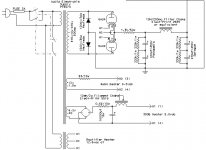
Here is the original:
And the Welborne:
The welborne removes some of the parts in the audio path too... and it only uses one side of the 6N1P unless I am mistaken. What's strange is I tried finding all the parts they include in their kit, but they don't sell them all on their parts page... such as the ASC Oil cap.
Anyone here know what values are used in the welborne schematic?
Here is the original:
An externally hosted image should be here but it was not working when we last tested it.
And the Welborne:
An externally hosted image should be here but it was not working when we last tested it.
The welborne removes some of the parts in the audio path too... and it only uses one side of the 6N1P unless I am mistaken. What's strange is I tried finding all the parts they include in their kit, but they don't sell them all on their parts page... such as the ASC Oil cap.
Anyone here know what values are used in the welborne schematic?
Mach_Y said:I contacted handwoundtransformers.com as well to see if they can do it. Dropping down the gain (and B+ to 550 from the original 700VDC) doesn't seem like a bad idea to me. There are other differences as well...
Here is the original:
An externally hosted image should be here but it was not working when we last tested it.
And the Welborne:
An externally hosted image should be here but it was not working when we last tested it.
The welborne removes some of the parts in the audio path too... and it only uses one side of the 6N1P unless I am mistaken. What's strange is I tried finding all the parts they include in their kit, but they don't sell them all on their parts page... such as the ASC Oil cap.
Anyone here know what values are used in the welborne schematic?
Mach:
The welborne schematic is the same as the EP schematic. If you look at the 6N1P you will notice dual pin numbers on each section. He just doesn't show the other triode in the tube. On the EP schematic it shows the change in the value of the cathode resistor for the use of the 6N1P. I would try to build this as EP shows it and experiment with lowering the voltage with the circuit as is and go from there. There does seem to be a couple of slight differences in the power supply, mostly added resistors in the filter section which would lead me to believe that Welborne just turned down the voltage on her and wished it well. It's the easiest shot to take anyway, and the guy from welborne will use someone else's design lock, stock, and barrel. Don't misunderstand me, he pays for the rights so I'm not knocking him and he buys the best stuff. Handwound transformers are okay to use if you have the time to wait on them. It will take anywhere from 1 month to 6 months worst case. I don't know about you, but I'm plotting this one. I gotta hear it.
Hate to be devil's advocate but...
That schematic looks very much like the Bottlehead Afterglows. Except the afterglows use a solid state CC source in place of the choke, and come right off of the cathode. Sound is very clean and linear. Deep bass. The other thing is the use of the 2A3, not 300b.
So now my question... are we not using the 300b as an amp, but as an anode follower? Seems to me that we are not using the full B+ for the output. One must subtract the voltage at the point that is feeding the choke/grid/6N1P anode from the B+ to come to the usable signal voltage for the output. So if it is about 150 volts, and B+ is 550 volts, with no bypass at the cathode, usable signal output will be 400 V P-P. I guess.
Also... 550 volts at the anode of the 300b... that's pushing it a little, no?
As for Handwound... three months seems the norm.
Gabe
Yes, this amp is the same as the Welborne Labs, but with permission from Jack Elliano of Electra-Print.
The first DRD amp that I built for a friend of mine was from a kit building class from the Randall Museum in San Francisco. That kit includes everything for $940.00 excluding the 300B tube. Registration is $130.00. Anyway, they have Electra-Print ST3 OPT, power tranny and filament choke from Transcendar, Electra-print choke for the driver and uses solid state rectifier. 2x40uf ASC oil Caps and the biggest difference is that they use a 6AN4 tube as the driver tube, according to Jack Elliano, this tube actually sound better than the 6N1P or 6AQ8 and its cheap. Another thing I noticed is that the B+ on the Welborne Labs is only 550v whereas the amp that I built are around 720v.
The Second DRD amp I build for myself, I just finished this week uses 6AN4 as the driver tube, All Electra-Print Transformers and chokes except the power transformers which is from Audio Electronics Supply, 60uf ASC Oil Cap and a 22uf GE Oil Cap connected in parallel. The rectifier is hybrid, the PS Tranny is rated at 375-0-375, so what I did to get 700v is build a bridge with 2 solid state Hexfreds to ground and 2 6AU4 to B+. This works, but how good is ???. All this parts that I build my amp from are from my previous projects, except the chassis that a friend of my build. I will post a photo as soon as I got one.

Gabevee said:
Also... 550 volts at the anode of the 300b... that's pushing it a little, no?
Gabe
That's something that I don't understand as well, but my reason is due to ignorance. How does one get around using excessive voltage on the plate? I noticed that on the 2A3 design as well and most of the time my voltages wind up being higher than maximum plate voltage. The schematic from EP shows a B+ voltage of 700 volts with 705 volts on the plate, 280 volts on the cathode and 198 volts on the grid.

Forgot to say, the modification to the Randall Amp to use 6AN4 were done by John Atwood. He gets the credit.
The 500v or 700v or any voltage B+ on a tube is referenced on the ground, the tube operating voltage is measured ACROSS the tube, so on this amp, as in my circuit, the voltage across the 300B is around 450v, even though the B+ measured is 720v but it is reference from the ground. As you can see the cathode is 270v, reference from the ground. The tube is operating at around 450v at 85ma, tube dissipation is 450 x .085 = 38.25 watts, which is below the rated plate dissipation of 40w.
Operating the tube at 550v will lower the grid voltage which is in turn is the plate voltage of the driver, which may be to low. This circuit may be simple, but it is complex to adjust as the operating point of the 300B depends on the operating point of the driver.
But once adjusted, boy, you will be in musical nirvana or whatever you call it.
Alex
cdeveza:
Your schematic looks good... I am interested to hear how the sound is with the power supply like that though... could you by chance post a parts list / price / where you bought the stuff from? Pictures would be great too 🙂
The signal section of the schematic I like a lot... it only has 2 tubes and 1 transformer in the signal path... it eliminates the resistors completely. Doesn't get much simpler.
This amp I built for myself was made from parts I already have from my previous project. Although the PSU works, I do not recommend doing it, if you still have to buy a power tranny. What I do recommend is to follow the power supply from the original schematic and get the power tranny from Electra-Print or have somebody wind it for you, with that same spec. Follow my main amp circuit schematic though using the 6AN4 as driver tube. Also, on the 300b cathode, there is a divider network. The original schematic from the randall museum uses an adjustable power resistor made by Ohmite, with two wiper, one connected to the driver choke and the other to ground, my circuit uses two 750ohms/25watts rheostat, these are used to adjust the operating point of the 300B and the driver tube. It is easier to adjust using these rheostat than using an adjustable resistor in which you loosen up the screw that holds the wiper and then moving it up or down. Also you have to do this when the power is off, while using a rheostat, you can adjust while power is on. The only disadvantage is that the rheostats are expensive, I got mine from a surplus store for $12.50 a piece, and you need 4 of them.
Here are the major parts you need:
1 x Electra-Print OPT ST3KB (do not substitute)
1 x Electra-Print Choke 65H/20ma (driver load, do not substitute)
2 x ASC 40uf/440vac Polypropylene Oil Caps (From Allied Elec, do not substitute, connect in parallel to make 80uf)
1 x 5k/50w adjustable resistor with 2 wiper (Ohmite or equivalent)
110ohm/ 1/2watt resistor (metal film, driver cathode)
100uf/16v electrolytic cap (recommend black gate, but any good brand is ok, driver cathode by-pass)
47k/ 1/2watt resistor (metal film input load)
300B tube (I like the JJ)
6AN4 tube
1 x power tranny: 575v-0-575v 250ma, 5v/2a, 7.2v/2a, 6.3v/.5a Electra-print or equivalent)
10H/200ma choke (Electra-print or equivalent)(Electra-Print cheaper than hammond)
30mh/1.4a filament choke (Electra-print or equivalent)
2 x 6AU4 (rectifier)
2 x 100uf/450v (panasonic digikey or equivalent)
2 x 470uf/450v (panasonic digikey or equivalent)
2 x 10000uf/16v (for 300b heater)
4 x 330k/1w bleeder/balancing resistor
1 x 50ohm/5w resistor
1 x 4A 50PIV bridge rectifier for 300b heater
1 x 0.68ohm/3w for 300b heater (to lower the voltage a bit)
Ok, there you go, these are for one channel only, so multiply by two to make stereo. The only thing missing are the hardware and chassis.
1 x 6.8 ohm/3w for 6AN4 heater (to lower the voltage a bit)
Follow my main circuit schematic except the 300B cathode resistor assembly, just use a simple adjustable resistor and you should be ok. Follow the original power supply schematic, not mine as mine is sort of jury rigged.
Good Luck...
Alex Deveza
To, cdeveza & Mach_y.
this several day I directly run in this amp & test the continous condition, stable or not for the coming kit over 30 hours.
( Transformer couple 300B/2a3/45 amp)
I still use 6C45/we437a Single triode to driver the Tango NC 16 to drive 300b with James Choke & output.
I also keep this in a very reasonable price. But I must make sure it will very stable to make the user not disappointed.
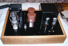
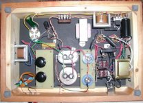
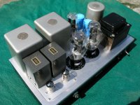
pls see the photos.
I reference this circuit & only a littler change it then more reasonable price<USD 1200 can get it. With all famous transformers. I also use 99.99 pure solid silver core to connect the ground. Its really very slient.
The sound is much better than my friend's audionote amp.
I really satify.
this circuit. http://www.tubebuilder.com/images/schematics/singleended/we300b_se4.gif
thanks
thomas
this several day I directly run in this amp & test the continous condition, stable or not for the coming kit over 30 hours.
( Transformer couple 300B/2a3/45 amp)
I still use 6C45/we437a Single triode to driver the Tango NC 16 to drive 300b with James Choke & output.
I also keep this in a very reasonable price. But I must make sure it will very stable to make the user not disappointed.
pls see the photos.
I reference this circuit & only a littler change it then more reasonable price<USD 1200 can get it. With all famous transformers. I also use 99.99 pure solid silver core to connect the ground. Its really very slient.
The sound is much better than my friend's audionote amp.
I really satify.
this circuit. http://www.tubebuilder.com/images/schematics/singleended/we300b_se4.gif
thanks
thomas
Attachments
Alex,
Thanks for the informative post. I'm still curious as to how it sounds? 🙂
Any reason why the output and driver load chokes must be EP brand? Is something different about theirs? Not being critical, just curious and trying to learn.
Thomas: The schematic you referenced has more parts in the signal path than the direct drive schematic provided by Alex. Your schematic has the signal passing through a variable resistor (pot) and the transformer. Also, with the resistor / capicitor dropped down between the input tube and driver tube, you have lost the constant current source provided by the transformer alone between the two. That being said I have no personal experience saying that your design would not sound as good as the other, but much has been said for the sound of the other design, and the theory behind it makes perfect sense.
I also wouldn't mind possibly building both and comparing them 🙂
You have email Thomas.
- Status
- Not open for further replies.
- Home
- Amplifiers
- Tubes / Valves
- which 300B project? help please