It was the 2N3791-2 that was made available in 1966, that was the first powerful Motorala pnp transistor available at the time. This is what they both had to use. I used it too, in 1967, until 1969, when better transistors became available. These were EXPENSIVE devices, as I said before.
P.S. Mean you the class-D amp "X-10" from the attachement?
Planet Sinclair: Audio: Amplifiers: X-10
Does someone have a complete and readable schematic for this amplifier?
And here a diy concept from 1966:
Popular Electronics Magazine, September 1966
As my brain has stalled, someone enlighten me on the role of C8 - is it just providing degenration around the PNP?
C8 looks like a bootstrap to try to maintain constant voltage across the transistor as the output voltage swings.
The Motorola types 12536 and 12537 maybe the JBL/Lansing lableling versions of the 2N3791/2N3792. The SA-600 and SA-660 are also from 1966.It was the 2N3791-2 that was made available in 1966, that was the first powerful Motorala pnp transistor available at the time. This is what they both had to use. I used it too, in 1967, until 1969, when better transistors became available. These were EXPENSIVE devices, as I said before.
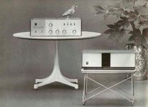
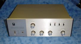
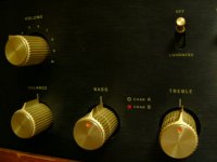
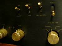
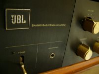
Here some URLs, schematics and pics to Lansing's SA-600:
JBL SA-600
http://www.jblproservice.com/pdf/Vintage JBL-UREI Electronics/JBL-SA600~SA660.pdf
http://www.diyaudio.com/forums/analogue-source/108986-jbl-sa600-sa660-integrated-2-ch-amps.html
JBL SA600 & 660 Service Manual free download,schematics,datasheets,eeprom bins,pcb,repair info for test equipment and electronics
Totale restauratie van een JBL SA-600 versterker uit 1966
http://users.ece.gatech.edu/~mleach/papers/tcir/tcir.pdf
go also to ebay item number 330428862602
Attachments
-
 JBL SA-600 b-w.jpg50.8 KB · Views: 808
 -
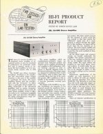 JBL SA-600 Lab Test electronic world 1966.jpg145.4 KB · Views: 792
 -
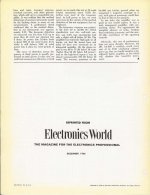 JBL SA-600 Lab Test electronic world II 1966.jpg80.6 KB · Views: 771
 -
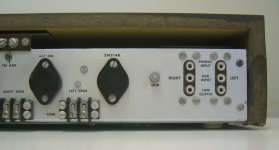
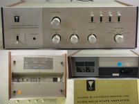 JBL SA-600 front rearx2.jpg61.7 KB · Views: 766
 -
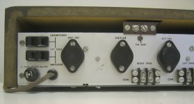
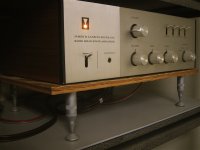 JBL SA-600 front left.jpg176.1 KB · Views: 754
 -
 JBL SA-600 left.jpg194.4 KB · Views: 236
 -
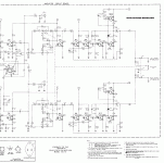
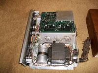
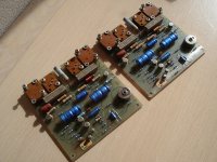 JBL SA-600 Power Amp PCB.jpg278.2 KB · Views: 316
 -
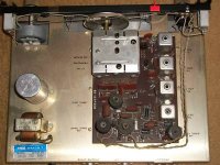
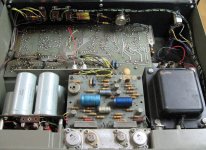 JBL SA-600 open top view.jpg123.3 KB · Views: 358
 -
 JBL SA-600 Mot 12536 12537.jpg43.4 KB · Views: 363
 -
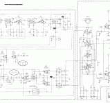
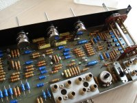 JBL SA-600 Preamp PCB.jpg270.6 KB · Views: 321
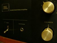
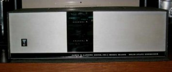
Now the SA-660, also from James B. Lansing
JBL SA-660
ƒI�[ƒfƒBƒI�C—� �b JBL SA660 ƒvƒŠƒ�ƒCƒ“ƒAƒ“ƒv‚Ì�C—�
go also to ebay item Number 180497815167
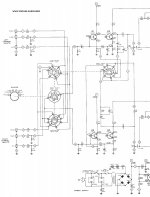
in the schematic I note, that an inverted mode (instead the most to find non inverting mode) was chosen. Mr. Boothroyd Stuart, the developer from the first Meridian components also prefer this mode by his amplifiers. He claim, that only in this mode the complete circuit is in the NFB loop. I think the same. The disadvantage of the lower input resistance isn't a problem in real life, except I have a pre amp tube driver and high output impedance.
here more infos:
http://www.harman.com/EN-US/OurComp...ip/Documents/Scientific Publications/1091.pdf
JBL SA-660
ƒI�[ƒfƒBƒI�C—� �b JBL SA660 ƒvƒŠƒ�ƒCƒ“ƒAƒ“ƒv‚Ì�C—�
go also to ebay item Number 180497815167
in the schematic I note, that an inverted mode (instead the most to find non inverting mode) was chosen. Mr. Boothroyd Stuart, the developer from the first Meridian components also prefer this mode by his amplifiers. He claim, that only in this mode the complete circuit is in the NFB loop. I think the same. The disadvantage of the lower input resistance isn't a problem in real life, except I have a pre amp tube driver and high output impedance.
here more infos:
http://www.harman.com/EN-US/OurComp...ip/Documents/Scientific Publications/1091.pdf
Attachments
-
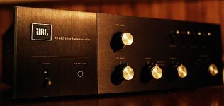 JBL SA-660.jpg25.9 KB · Views: 455
 -
JBL SA-660 terminal.pdf68.8 KB · Views: 245
-
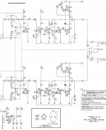
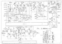 JBL SA-660 schem.jpg316.6 KB · Views: 488
 -
 JBL SA-660 right front.jpg128.4 KB · Views: 224
 -
 JBL SA-660 mid front.jpg130.8 KB · Views: 157
 -
 JBL SA-660 mid front II.jpg128.1 KB · Views: 145
 -
 JBL SA-660 inside.jpg107.3 KB · Views: 239
 -
JBL SA-660 botton.pdf94.5 KB · Views: 230
-
 JBL SA-660 left front.jpg124.7 KB · Views: 180
Last edited:
Am rebuilding one of these 660 on my bench. WOW, what a pain to work on. All kinds of bad parts. Looks like a very sound design though save for all the cap coupling. The power amp part is pretty good.
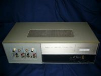
JBL SE-400/SE-408 - Lansing's Power Amplifiers (Energizer's)
sumaudioguy, use good quality caps between 63-100 VAC and 105 degrees from brands like Rifa/Evox, BHC-Aerovox or Mallory. If physical only 10VAC or 25VAC necessary, use nevertheless 63VAC, because the ESR is lower. If the space to large, use half of capacity (470uF/63V is still better than 1000uF/25V). Replace all caps.
URLs to JBL SE400/SE408
http://www.jblproservice.com/pdf/Vintage JBL-UREI Electronics/JBL-SE400S_SE408S.pdf
Vintage JBL-UREI Electronics
Jbl C44 Paragons Info Please Please - Page 3 - AudioKarma.org Home Audio Stereo Discussion Forums
various JBL SA/SE series are compatible with Crown models - read more here:
http://www.jblproservice.com/pdf/Electronic Products List/08EPL.pdf
The schematics are all online. Unfortunately not for the older models SE-401 and SE-402, equipped with germanium power devices. Who knows, why? - go to post #46 about
http://www.diyaudio.com/forums/soli...-amplifier-components-want-5.html#post2200095
for pics of this amps
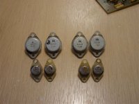
On the second pic you will discover RCA types instead Motorola. This means, that also RCA at this time introduce true complementary power devices, perhaps at this first time exclusively for certainly brands like Lansing/JBL, McIntosh and Crown.
sumaudioguy, use good quality caps between 63-100 VAC and 105 degrees from brands like Rifa/Evox, BHC-Aerovox or Mallory. If physical only 10VAC or 25VAC necessary, use nevertheless 63VAC, because the ESR is lower. If the space to large, use half of capacity (470uF/63V is still better than 1000uF/25V). Replace all caps.
URLs to JBL SE400/SE408
http://www.jblproservice.com/pdf/Vintage JBL-UREI Electronics/JBL-SE400S_SE408S.pdf
Vintage JBL-UREI Electronics
Jbl C44 Paragons Info Please Please - Page 3 - AudioKarma.org Home Audio Stereo Discussion Forums
various JBL SA/SE series are compatible with Crown models - read more here:
http://www.jblproservice.com/pdf/Electronic Products List/08EPL.pdf
The schematics are all online. Unfortunately not for the older models SE-401 and SE-402, equipped with germanium power devices. Who knows, why? - go to post #46 about
http://www.diyaudio.com/forums/soli...-amplifier-components-want-5.html#post2200095
for pics of this amps
On the second pic you will discover RCA types instead Motorola. This means, that also RCA at this time introduce true complementary power devices, perhaps at this first time exclusively for certainly brands like Lansing/JBL, McIntosh and Crown.
Attachments
-
 JBL SE408S front.jpg82.3 KB · Views: 148
 -
 JBL SE-408S open.JPG35.1 KB · Views: 173
 -
 JBL SE series overview.jpg74.3 KB · Views: 216
 -
 JBL SA-SEamps.datasheet.jpg97.5 KB · Views: 163
 -
 JBL SE400S front.jpg11.8 KB · Views: 151
 -
 JBL SE-400 front.jpg284.8 KB · Views: 147
 -
 JBL SE-400se rear.jpg8.3 KB · Views: 134
 -
 JBL SE-400SE front.jpg34.4 KB · Views: 141
 -
 JBL SE-400 rear.jpg24.5 KB · Views: 142
Last edited:
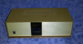
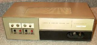
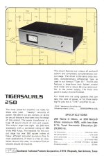
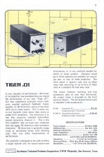
Power Amp Tiger.01 (Mono) and Tigersaurus 250, Stereo fr Southwest Technical Products
Not the really first true complementary PP buffer is inside. But the first version in this power aera with only one power devices pair (predecessors from Motorola's later released MJ802-MJ4502) - so I think.
Tigersaurus 250 Scan - AudioKarma.org Home Audio Stereo Discussion Forums
SWTPC Catalog - Circa 1980
Radio Electronics December 1973
Radio Electronics Vintage Magazine December 1973 by karensvariety
http://www.diyaudio.com/forums/solid-state/123047-tigersaurus.html
http://www.diyaudio.com/forums/solid-state/41926-universal-tiger.html
http://www.diyaudio.com/forums/solid-state/23706-has-anyone-here-built-slone-amp-tigersaurus.html
Attachments
Last edited:
sumaudioguy, use good quality caps <snip>
Yes got that covered. It is a real "cooker" (hot in cabinet) so 105 degree C is used throughout. For the dollar and in general have not been able to beat the Panasonic FM series. There are a lot that are more expensive but not many that are better.
I have built most of the SWTPC designs, and had no problems with them.
They sounded quite good, besting most commercial designs.
They sounded quite good, besting most commercial designs.
Please note that the part numbers are very high, and show that this parts list was 1970 or later. The 2N6031 was the PNP complement of the 2N5631 and was not available in late '60's as a 2N number. It was a specially processed 2N5884-6 series, to give better voltage breakdown with the tradeoff of worse beta linearity, and lower f(t). This was also used by SAE and GAS, as well as many other companies for several years.
It was the 2N3791-2 that was made available in 1966, that was the first powerful Motorala pnp transistor available at the time. This is what they both had to use. I used it too, in 1967, until 1969, when better transistors became available. These were EXPENSIVE devices, as I said before.
What were actually the benefits to the the most symmetric topology of all, the so-called Circlotron (also known under the terms PPP, SEPP, CSPP - that means parallel push pull, Single Ended Push Pull and Cross shunted push pull) both at those days and currently?
Until this day I haven't understand, why the so called "true complementary" topologies used from the most brands, while the Circlotron (which have most symmetric behaviour) was only used from SUMO (and perhaps currently only from BAT, Balanced Audio Technology, as I know).
The URLs regarded this patents are here: post #92, page 10 about
http://www.diyaudio.com/forums/soli...state-audio-amplifier-components-want-10.html
Last edited:
True complementary - Germanium meets Silicon (RCA 1964/1965)
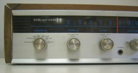
RCA's pair 2N2148/TA2577A and 2N2147/TA2577, both TO-3, used in various models from Heathkit arround 1964-1965.
Unfortunately no datasheet of RCA's silicon power device TA2577 (no Toshiba IC !!!) is to find. Factory number of Heathkit was "417-101"
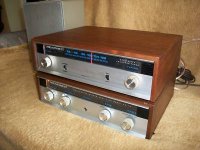
Here some URLs schemas and pics from Heathkit's receiver AR14 (AR-14):
Heathkit AR-14 in nearly new condition (very cheap - <$130):
ebay Item number: 230468551482
http://www.heathkit.se/files/AA-14.pdf
Swedish Heathkit Club - SK7XN
RCA's pair 2N2148/TA2577A and 2N2147/TA2577, both TO-3, used in various models from Heathkit arround 1964-1965.
Unfortunately no datasheet of RCA's silicon power device TA2577 (no Toshiba IC !!!) is to find. Factory number of Heathkit was "417-101"
Here some URLs schemas and pics from Heathkit's receiver AR14 (AR-14):
Heathkit AR-14 in nearly new condition (very cheap - <$130):
ebay Item number: 230468551482
http://www.heathkit.se/files/AA-14.pdf
Swedish Heathkit Club - SK7XN
Attachments
-
 Heathkit AR-14 front left.jpg98.8 KB · Views: 548
 -
 Heathkit AR-14 front right.jpg90.7 KB · Views: 561
 -
 Heathkit AR-14 front right-II.jpg121.2 KB · Views: 578
 -
 Heathkit AR-14 advertisement.jpg105.5 KB · Views: 527
 -
 Heathkit AR-14 model sticker.jpg93 KB · Views: 507
 -
 Heathkit AR-14 rear left.jpg101.9 KB · Views: 177
 -
 Heathkit AR-14 schem c.GIF100.1 KB · Views: 371
 -
 Heathkit AR-14 schem b.GIF103.6 KB · Views: 296
 -
 Heathkit AR-14 rear right.jpg109 KB · Views: 161
 -
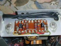
 Heathkit AR-14 solder site.jpg133.2 KB · Views: 293
Last edited:
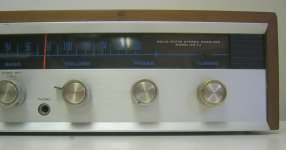
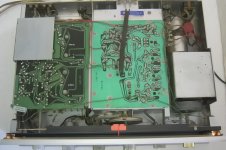
True complementary - Germanium meets Silicon (RCA 1964/1965) - II
Heatkit AA-14 and AJ-14 (tuner and integrated amp from model AR-14)
Heatkit AA-14 and AJ-14 (tuner and integrated amp from model AR-14)
Attachments
-
 Heathkit AA-14 +tuner.JPG17.9 KB · Views: 173
 -
 Heathkit AA-14 AJ-14 adv .jpg78.4 KB · Views: 148
 -
 Heathkit AA-14 AJ-14 type aera.JPG20.7 KB · Views: 130
 -
 Heathkit AA-14 front.JPG38.5 KB · Views: 160
 -
 heathkit AA-14 AR-14 2N2147, 50V 2N2148, 40V.jpg78.1 KB · Views: 180
 -
 Heathkit AA-14 AJ 14 tuner inside.JPG22.4 KB · Views: 158
 -
 Heathkit AA-14 insight.JPG21.6 KB · Views: 199
 -
 Heathkit AA-14 schem input.jpg234.1 KB · Views: 246
 -
 Heathkit AA-14 schem output.jpg242.3 KB · Views: 257
 -
 Heathkit AA-AJ-AR-14.jpg108.4 KB · Views: 263
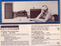
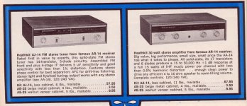
Wow, 15W (IHF) per channel.
I wonder if it could do more than 8W RMS per channel with both channels driven?
I wonder if it could do more than 8W RMS per channel with both channels driven?
Still, this was a pretty advanced design for its time.
by post #43 (page 5, RCA), #33, #34, (page 4, RCA) post #22, #23 (page 3)
about the thread
http://www.diyaudio.com/forums/parts/167680-vintage-transistors.html
I have posted some covers from various vintage data books. We know now the exact wording of the title and the year of release. Thus there is the possibility to order about a book store. Additional one can each of these books order through the interlibrary loan service about the local university library for the aim of rent and/or for the aim of copy the wanted data sheet sites.
Perhaps one of the members here can say, in which of the showed RCA data books the 2N2148/TA2577A and 2N2147/TA2577 is inside.
On the web only short form data sheets from Semelab (2N2147/2N2148) are to find. And about the TA2577/TA2577A nothing is to find.
Last edited:
🙁To bad... went through the library a few years ago and tossed all the pre-1975 data books, ugh!🙁
Saved the tube stuff though.😕
Saved the tube stuff though.😕
- Home
- Amplifiers
- Solid State
- What was the first Complementary AB bipolar amplifiers?