What other measure do you think you can use to lower the output impedance?
Feedback, more tubes, or an output transformer.
The gain is NOT 180!Whoops! I looked at the wrong equation when I calculated the gain of the cascode input stage... This is why I ask people if my numbers make sense. Thanks!
New attempt at dissecting the voltage gains in the M-60:
Input stage (6SN7 cascode):
gm = 2.7 mA/V
load resistor value Ra = 100 kOhm:
gain = gm x Ra = 270 (not 400 as in my previous post)
Driver stage (6SN7 cathode followers):
mu = 20
gain = mu / (mu+1) = 0.95
Output stage (6C33C "cathode followers" in the circlotron):
mu = 2.6
gain = mu / (mu+1) = 0.7
Total gain without feedback:
270 x 0.95 x 0.7 = 180 = +45 dB
According to the AtmaSphere website, the M-60 (with 6SA7 tubes) has a total gain of +20 dB. Ignoring the mu difference between the stock 6SA7 and your 6C33C tubes, this means there must be about -25 dB feedback in the M-60. 😕
Look at the picture with a cascode using 6SN7 and 100 Kohm anode resistor.
Gain ca. -50
Total gain without feedback 50 x 0.95 x 0.7= 33,25 Witch is about 30 dB.
1 dB feedback --- 29 dB gain and then some not calculated losses...
Believe me the amp without feedback has normal gain for a poweramplifier.
Attachments

The M-60 voltage amplifier has a bit more gain than the amp has overall due to losses in the cathode follower driver circuit and then again in the output section itself.
To run feedback on this, rather than mess with the linearity of the voltage amplifier by trying to get more gain out of it, I would leave it outside of the feedback loop, and capacitively couple it to a single differential gain stage like a 12AT7. I would then use the feedback to negate all the gain of that stage.
The problem you are up against here is unseen frequency poles that limit the phase margin of the circuit. Setting up feedback can be really tricky; if there is to be a lot then it can't be just a simple resistor! At any rate this method with the 12AT7 would get you about 20dB reliably but I think you'll find that to really get things to work you'll need more- 35-40dB (at which point the amp will have a nice low output impedance) but obviously the circuit lacks the gain bandwidth product to do this as it sits. 35dB is about the minimum you need to allow the circuit to compensate for the distortion caused by the application of feedback itself.
.
As for the cascode you making a mistake , the gain of this stage is aproximately the same as a common cathode stage , but with lower Miller capacitances and of course better high frequency response ! .
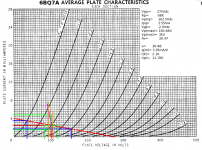
Only for solid state cascodes. For a BJT cascode, the upper transistor reflects re as the lower collector load so the gain of the lower BJT is: re/re or nearly unity gain. Hollow state cascodes offer more gain than the same CK stage would produce. Some loadlines:
The upper triode with a load of 68K manages a gain of 30.47, and reflects 2.1K to load the lower triode (orange loadline) for a gain of 5. The total gain is: 30.47 X 5= 152.35 -- considerably above the gain of a single 6BQ7A section, and well into small signal pentode level gain. Since this was for a cascode LTP, the gain is half that of one cascode: 76.175 -- more than enough to eliminate a second gain stage.
The CK first stage does indeed have much less CMiller. From the spec sheet of the 6BQ7A, Crt= 1.2pF, so CMiller= (5 + 1) X 1.2= 7.2pF. Also within pentode territory. The effective rp= 11.35E3 X (1 + 36.88)= 429.938E3. This gives a -3dbv= 117KHz -- again, more like a resistor loaded BJT voltage amp, or a pentode voltage amp.
The one thing you need to be aware of is to make sure the nearly vertical loadline allows enough swing without clipping to drive the output to the necessary swing.
You don't need dual triodes for a cascode, nor do they have to be the same devices. You can cascode a FET lower + triode upper, or implement a folded with triode on the bottom and BJT up top for lotsagain if you need it.
Attachments
Only for solid state cascodes. For a BJT cascode, the upper transistor reflects re as the lower collector load so the gain of the lower BJT is: re/re or nearly unity gain. Hollow state cascodes offer more gain than the same CK stage would produce. Some loadlines:
The upper triode with a load of 68K manages a gain of 30.47, and reflects 2.1K to load the lower triode (orange loadline) for a gain of 5. The total gain is: 30.47 X 5= 152.35 -- considerably above the gain of a single 6BQ7A section, and well into small signal pentode level gain. Since this was for a cascode LTP, the gain is half that of one cascode: 76.175 -- more than enough to eliminate a second gain stage.
The CK first stage does indeed have much less CMiller. From the spec sheet of the 6BQ7A, Crt= 1.2pF, so CMiller= (5 + 1) X 1.2= 7.2pF. Also within pentode territory. The effective rp= 11.35E3 X (1 + 36.88)= 429.938E3. This gives a -3dbv= 117KHz -- again, more like a resistor loaded BJT voltage amp, or a pentode voltage amp.
The one thing you need to be aware of is to make sure the nearly vertical loadline allows enough swing without clipping to drive the output to the necessary swing.
You don't need dual triodes for a cascode, nor do they have to be the same devices. You can cascode a FET lower + triode upper, or implement a folded with triode on the bottom and BJT up top for lotsagain if you need it.
Thank you Miles P. for this post , in fact it have been a long time that I didn't experiment with cascodes , so I forgot alot about them , and I don't like em very much cuase they have high output impedance ( equal to the load resistor of the upper triode as you know ) . When made my first OTL back in 2004 and since then , in all my amps and preamps , I use two gain stages , that allow me to use a local NFB in each stage and a GNBF in the whole amp and of course a lot of fine tuning ! .
The gain is NOT 180!
Look at the picture with a cascode using 6SN7 and 100 Kohm anode resistor.
Gain ca. -50
Total gain without feedback 50 x 0.95 x 0.7= 33,25 Witch is about 30 dB.
1 dB feedback --- 29 dB gain and then some not calculated losses...
Believe me the amp without feedback has normal gain for a poweramplifier.
Your calculations are close to reality , but as Miles P said , the gain of the coscode LTP is half the gain of one cascode , therfore we have 25 x 0.95 x 0.7 = 24dB and with loses due to high output impedance of the cascode and NFB we came close to the 20 dB of the amp .
Last edited:
You are of course right, forgot the LTP.Your calculations are close to reality , but as Miles P said , the gain of the coscode LTP is half the gain of one cascode , therfore we have 25 x 0.95 x 0.7 = 24dB and with loses due to high output impedance of the cascode and NFB we came close to the 20 dB of the amp .
Thank you Miles P. for this post , in fact it have been a long time that I didn't experiment with cascodes , so I forgot alot about them , and I don't like em very much cuase they have high output impedance ( equal to the load resistor of the upper triode as you know ) . When made my first OTL back in 2004 and since then , in all my amps and preamps , I use two gain stages , that allow me to use a local NFB in each stage and a GNBF in the whole amp and of course a lot of fine tuning ! .
the lower tube is chosen for transconductance, since the gain is gm x Rl, the upper tripod not so much....so they can be different tubes...
say a 6dj8 at the lower triode and a 6cg7 as upper triode...
cascodes are like doing a pentode sans the pentode transition noise, useful at rf but at af i am not so sure...
since output impedance is high, stray capacitance will hit gain at hf....
since output impedance is high, stray capacitance will hit gain at hf....
Yes without partition noise of the pentodes and with lower distortions ! , their high frequencies respopnse is good because we have two tubes in series and the transfer capacitance are divided .
The reason for the differential cascode is simple. The amp is very transparent; its best to keep coupling capacitors at a minimum. The problem is that a differential cascade amplifier gets in real trouble if the gain stages are direct-coupled. You can place a pot in the circuit to adjust for the mismatches in the tubes. The most effective location is the cathode of the first gain stage. But it doesn't work that well, the cure being worse that the illness.
So I went to the differential cascode. There are a different set of problems, but in a nutshell enough gain and bandwidth to do the job. Distortion is lower, owing to that pesky adjustment in the cascade circuit I mentioned. And its easy to find suitable tubes in the field without a lot of fiddling and matching.
So I went to the differential cascode. There are a different set of problems, but in a nutshell enough gain and bandwidth to do the job. Distortion is lower, owing to that pesky adjustment in the cascade circuit I mentioned. And its easy to find suitable tubes in the field without a lot of fiddling and matching.
I wonder if we place ( for example ) a 470 Ω resistor between the anode of the lower and the cathode of the upper tube ( which works as a common grid amp ) , to have some degenerative feedback , will we have even lower distortions ? .
You really want that bottom tube to have its best shot driving the top tube. You can get more gain and the like with other setups but when you factor in reliability and the ability to use a wide range of tubes the configuration as we've been using it has won out.
cascodes are like doing a pentode sans the pentode transition noise, useful at rf but at af i am not so sure...
There is a definite lack of how hollow state, AF cascodes perform. That was the A Number One problem I had when working out the Le Renard design: nothing about audio cascodes except for a mention in guitar amp practice where the goal was gain, not sonic performance. It was another case of try and listen. It wasn't until much later I found an example in the wild: Hedge Amp.
Cascodes are used a lot in SS audio designs to fix the voltage across the lower transistor for less distortion, so I figured it would work the same for triodes, and it definitely does. It proved to work very well as a cascoded LTP. (Used 6BQ7A -- designed for VHF cascode duty. No mention of AF, but good audio loadlines can be found for the type.
since output impedance is high, stray capacitance will hit gain at hf....
It's the total plate resistance that determines this: rp || RP. Why hollow state wideband operation is more difficult than with solid state. With BJTs, you can drive up the gm with the only limit being melting the die. You can get useful voltage gains from ~100R collector resistors. Modern FETs also have sky high gm -- way more than any VT.
In the early ´80 I designed a commercial hybrid tube/MOSFet amp with a cascode (ECC88) voltageamp input and a triode coupled ECL82 (only used the L part) as cathode follower to drive the MOSFet´s.There is a definite lack of how hollow state, AF cascodes perform. That was the A Number One problem I had when working out the Le Renard design: nothing about audio cascodes except for a mention in guitar amp practice where the goal was gain, not sonic performance. It was another case of try and listen. It wasn't until much later I found an example in the wild: Hedge Amp.
Cascodes are used a lot in SS audio designs to fix the voltage across the lower transistor for less distortion, so I figured it would work the same for triodes, and it definitely does. It proved to work very well as a cascoded LTP. (Used 6BQ7A -- designed for VHF cascode duty. No mention of AF, but good audio loadlines can be found for the type.
It's the total plate resistance that determines this: rp || RP. Why hollow state wideband operation is more difficult than with solid state. With BJTs, you can drive up the gm with the only limit being melting the die. You can get useful voltage gains from ~100R collector resistors. Modern FETs also have sky high gm -- way more than any VT.
In the matching preamp , the riaa was very inspired from the Marantz 7 but with a cascode coupled ECC8 as first stage. Later, in order to have enough gain and little enough noise I put a JFet (2SK147) in the chatode part of the lower ECC88 cascode , fixing its grid at about 12 V.
Very low noise and very good sound from this combo.
Hi Koldby, you have any pics of schematics?
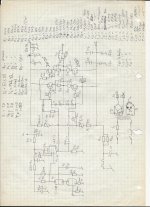
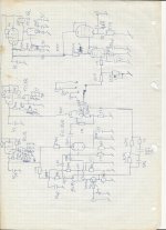
Dusting around in the old acrehives, I came up with this.
I made these under the brand name Audio Mirror looooong before anybody had thought about starting the american company with the same brand name..
Power amp was TFA3 (Tube Fet Amplifier) and preamp TPA4a (Tube Pre Amplifier) The "a" suffix was the J-Fet upgrade. As can be seen I had a pretty elaborated PS regulation in the Preamp and of course the filament supplies was too with lifted potential where it was needed, to avoid filament to cathode problems.
Attachments
Thanks dear Koldby
You are welcome!
As Esteban points out to me, there is no need for the MOSFet source resistors and they were not used in the production units either. This schematic is a very early prototype and some changes were made. Don´t recall all of them though. I might have a more resent schematic
- Home
- Amplifiers
- Tubes / Valves
- What tubes for a OTL tube amp?