I noted a noise figure of 50 nV/rt Hz on the chopper stabilized amp. That's about 1 uV over a 300 Hz BW.
I think you can get to 100 pV/rt Hz using some (un)conventional tricks but much below this and it starts to get difficult.
I think Joachim has some stuff cooking in the kitchen that might be interesting
Fascinating reading - incredible technology - thanks for sharing George.
Choppers have come a long way. Some low noise choppers that are now available:
MAX44250: 5.9nV/rtHz
ADA4522: 5.8nV/rtHz
OPA2188: 8nV/rtHz
None come close to what is required at Ligo though. I've got to admit I'm jealous of the engineers that get to work on that problem!
You can check out a couple of composite designs here on diyaudio, myref (open source, looks like several versions) and modulus-86 (commercial and schematic not available, though the creator has written about various aspects of its design in different threads). They both use a LM3886 audio power amplifier with an opamp in the feedback path to substantially reduce distortion over using just the LM3886 by itself.So it is not like 2 amps inside a single opamp IC then?
Yes, cascading two high-gain devices is a whole lotta gain, and stability is a major design consideration. The idea is to use a good characteristic of one amp (very low distortion) and another good one of the other (high output power) that aren't seen together in a single opamp, while keeping the whole thing stable.
Last edited:
Do you have any link for similar circuit like yours? I would like to try it if the JFET is not complementary.
Essentially this: JFET/NE5534 Composite Op Amp Photo by mtlin12 | Photobucket
You can check out a couple of composite designs here on diyaudio, myref (open source, looks like several versions) and modulus-86.
I have built the My Refs (Mauro Penasa's and Linuxguru) along with my own variations.
Hmmm... I think it will be too noisy... May be will worth it if coupled with power opamp (LM3886 etc).
But I still have no idea what's wrong technically with NE5532. It's boring and fatiguing character, when the slew rate is not that fast. If the fatigue is due to instability, what factors affect stability other than speed?
I looked into the equivalent circuit of NE5534 and I think the problem is with the internal compensation circuitry (caps). This is to ensure stability and high bandwidth with gain 3x or greater....
In other words, the high bandwidth and stability (unity gain BW up to 10MHz with 22pF compensation) is "fake"! The 22pF will cause a slew rate drop from 13 V/us to 6 V/us!
Hmmm... I think it will be too noisy... May be will worth it if coupled with power opamp (LM3886 etc).
😕
We're talking something that you can turn into << 1 nV/rthz if you play your cards right.
Low Noise Design Schematics
http://www.analog.com/library/analogdialogue/archives/47-10/discrete_amplifier.pdf
Besides, when I look into newer JFETs specifically from Vishay, there are many that have much lower noise and better linearity than the standard K170/J74
Which are? Inquiring minds want to know.
And "better linearity", you can't resist TTYH, isn't it?
Thanks.The LIGO site has full public access to some of the data sets/algorithms, just search around the site https://www.ligo.caltech.edu/WA/page/scientists. I personally don't understand what the theoretical physicists are saying but since the waves are much stronger as things spin faster they loose early data at low frequencies. There is also a desire to measure the background which I think they are far from.
Interesting stuff.
Dan.
Which are? Inquiring minds want to know.
It has been a long time ago. Not many but only one. Can't do the web searching right now. I think the limitation was too low Idss.
Thanks Daniel Andrew and Mark.
Scott has pioneered the composite amplifier configuration
But I asked there because I thought that by ‘composite’ Scott was meaning a configuration tried by LIGO engineers, where a chopper stabilized amp is nested with an op amp inside a feedback loop, like having a chopper stabilized amp (a composite amp itself) in place of one of the op amps in Fig 1 of LT App. Note 21 (I don’t know if this is doable, sorry for the noise)
http://electronicdesign.com/site-fi...lectronicdesign.com/files/29/21449/fig_01.gif
http://cds.linear.com/docs/en/application-note/an21f.pdf
George
Attachments
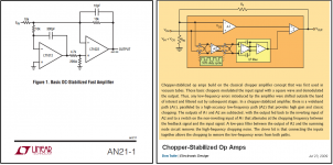
I've seen this done before where the chopper opamp drives the offset nulling pins of the fast opamp and also in the way shown in the diagram you have attached- so in a nutshell, yes it has been done before.
In your 1st attached diagram, there is a 250 Ohm resistor from the +ve input to GND - that's about 10nV/rt Hz. So any technique being used will have to consider effects like this which can completely swamp amplifier noise.
In your 1st attached diagram, there is a 250 Ohm resistor from the +ve input to GND - that's about 10nV/rt Hz. So any technique being used will have to consider effects like this which can completely swamp amplifier noise.
He is busy with speaker design right now 😉
Take a look at his MPP in the Analog Source forum - lots of ultra lo noise stuff for MC applications.
Choppers have come a long way. Some low noise choppers that are now available:
MAX44250: 5.9nV/rtHz
ADA4522: 5.8nV/rtHz
OPA2188: 8nV/rtHz
None come close to what is required at Ligo though. I've got to admit I'm jealous of the engineers that get to work on that problem!
Yes - that is good - I have not looked at chopper stabilised opamps since about 1989/90.
🙂
Okay, okay...
My point, I knew it was hard to see the "importance", is that IT people are conditioned to become learning machines. They may be also forced to be more selective in their learning/reading...
No different from Physics people, engineering people etc. Technical university courses should focus on teaching people how to learn. Programmers (who may come from other disciplines) are just part of that. At least good programmers. There are many bad ones being churned out who just copy off stack overflow rather than learning their craft.
As for Android. Well that's a linux fork with lots of Java. Nothing really new just nicely packaged.
Is that actually a composite in the purest sense? I can't see the JFETs inside the feedback loop. </pedant>
Technical university courses should focus on teaching people how to learn.
Wow! That's a very good idea. Did they teach you that in university?? I taught myself auto-didactically.
As for Android. Well that's a linux fork with lots of Java. Nothing really new just nicely packaged.
The concept is different. Because we have lots of limitation with handheld devices (such as memory size). Conceptually, any programming is similar, but the point is you cannot develop an android application only by reading/knowing Java and Linux. You have to read/learn another extra knowledge (even a new Integrated Development Environment; imagine if Google Inc. made Eclipse or old IDE unusable)
Hmmm... I think it will be too noisy... May be will worth it if coupled with power opamp (LM3886 etc).
😕
We're talking something that you can turn into << 1 nV/rthz if you play your cards right.
Hmm... I doubt that. Remember that in preamps we don't need gain. Maximum I would need is 3x (and that puts 5534 at the border of its stability). That's why I think it may worth it if coupled with high gain power opamp (LM3886)...
1 nV/rtHz is the voltage noise of a single K170. System noise will be higher than that. If the gain requirement of 3x is all taken by NE5534, what will be the gain of the JFET input stage? One. In buffer arrangement the system noise is not only determined by the input JFET but also shared by NE5534 noise (especially when the opamp is non-inverting)...
The PSRR will suffer too (even tho ccs and cascode is used). Power supply will have its noise contribution...
Now let's look into your implementation of the JFET input stage, to see how many more noises are added to the system:
(1) Bias current (ccs) seems to be quite high for the LTP of K170. Depletion JFET used in the current source might be low noise, but look at the BJT which takes almost full of the LTP bias current. This has contribution to the system noise...
(2) The LTP and trace capacitance will add instability to the system. Compensation might be needed in the form of (a) gate resistor that increase thermal noise (b) RC between opamp input pins that limit the slew rate of large signal at the input.
(3) K170 has high Vgs variation. This creates high input offset. Okay, gain is low so output offset will be low too. But can a capacitor be omitted from the input?
In your 1st attached diagram, there is a 250 Ohm resistor from the +ve input to GND - that's about 10nV/rt Hz.
2nV/rtHz
- Status
- Not open for further replies.
- Home
- General Interest
- Everything Else
- What is wrong with op-amps?