I think Joachim has some stuff cooking in the kitchen that might be interesting
He is busy with speaker design right now 😉
Take a look at his MPP in the Analog Source forum - lots of ultra lo noise stuff for MC applications.
All right, may be it is my mistake. I thought you were confusing Gerhard with Joachim Gerhard 🙂
so in a nutshell, yes it has been done before.
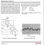
Yes. There is one, further down the LT AN21
🙂
George
Attachments
I taught myself auto-didactically.
Good for you.
The concept is different. Because we have lots of limitation with handheld devices (such as memory size). Conceptually, any programming is similar, but the point is you cannot develop an android application only by reading/knowing Java and Linux.
Riight, you clearly never went near a computer in the 90s. The average phone has more processing power and memory than a lot of unix systems back then. And more processing cores, and higher resolution screens etc.
If you know Java and Linux, and have a brain, you can pick up android dev fairly easily. Or you can cheat and use Xamarind. Really nothing hugely new, just the power available and the packaging.
Gents, after 121 pages, can someone answer this simple question - which is better, OPA134 or LME49710 ?

Really nothing hugely new, just the power available and the packaging.
Also worth noting that during the past 50 years we did nothing but replace IBM 3270 terminals with HTML terminals.Welcome to the cloud yay!!!!
😀
Yup things sure have advanced, even since the start of this thread in 2010.
Strangely my op-amps still appear to have nothing wrong with them though
Strangely my op-amps still appear to have nothing wrong with them though
Gents, after 121 pages, can someone answer this simple question - which is better, OPA134 or LME49710 ?
In terms of measured performance, the LME49710 will outperform an OPA134 unless it's used in a circuit where the input current noise is crucial (high source impedance applications).
We will now continue to argue for 121 more pages on whether or not that measured performance matters... 😛
In terms of measured performance, the LME49710 will outperform an OPA134 unless it's used in a circuit where the input current noise is crucial (high source impedance applications).
We will now continue to argue for 121 more pages on whether or not that measured performance matters... 😛
Of course it matters! 😛 If both opamps are recorded or used in a blind test, I believe that I will prefer LME49710. But I doubt that it is 100% because of the superior measurement... 😀
Also worth noting that during the past 50 years we did nothing but replace IBM 3270 terminals with HTML terminals.Welcome to the cloud yay!!!!
😀
If only. Most days I am using text only terminal sessions. But yes. Cloud, compuserve, spot the difference (other than pony tails)
In terms of measured performance, the LME49710 will outperform an OPA134 unless it's used in a circuit where the input current noise is crucial (high source impedance applications).
We will now continue to argue for 121 more pages on whether or not that measured performance matters... 😛
That we covered pretty well...
Can we take a detour and discuss it from a "constraints to the circuit" perspective. E.g. whether the lower input impedance of one would constrain you to using lower Rs and higher Cs, pushing you from C0G to large PP or even worse, in the electrolytics domain. Let's think "line level" stuff like tone controls.
Last edited:
Of course it matters! 😛 If both opamps are recorded or used in a blind test, I believe that I will prefer LME49710. But I doubt that it is 100% because of the superior measurement... 😀
Oh I don't necessarily disagree. I was only predicting that we won't reach a conclusion on which sounds better or why. The LME49710 is an exceptional performer in terms of measured distortion (and noise). But plenty here will discount that as a useless metric of sound quality and the argument will continue. 🙂
Continued improvement in audio products requires both parties because they drive the creation of new products and new attempts to measure and quantify any improvements those products bring.
However, although threads like this are fun, I worry that too many people spend more time arguing over trivial things like this than actually listening to music...
Can we take a detour and discuss it from a "constraints to the circuit" perspective. E.g. whether the lower input impedance of one would constrain you to using lower Rs and higher Cs, pushing you from C0G to large PP or even worse, in the electrolytics domain. Let's think "line level" stuff like tone controls.
Both opamps are considered to have measured performance above human ability to perceive. LME has better performance except probably at current noise. But current noise contribution is very low except when there is HUGE resistance in series with the input (to convert low current into high voltage). But in "line level" stuff there is no such HUGE resistance. Even the normal 10k pot in front of it will not generate high enough noise to be perceivable in an ABX.
But still, I'm sure I will be able to tell which one is which in an ABX 😉
That we covered pretty well...
Can we take a detour and discuss it from a "constraints to the circuit" perspective. E.g. whether the lower input impedance of one would constrain you to using lower Rs and higher Cs, pushing you from C0G to large PP or even worse, in the electrolytics domain. Let's think "line level" stuff like tone controls.
In my opinion JFET inputs really come in handy in a few places. First, MM phono preamps where the rising cartridge impedance at high frequency makes input current noise a significant contributor. JFETs also tend to have lower 1/f noise than lower priced CMOS amplifiers (compare OPA1642 (JFET) to OPA1652 (CMOS) which reduces the additional noise contribution from the high gain at low frequencies in the RIAA curve. OPA1642 makes a wonderful MM phono preamp for both these reasons. However, super-beta BJTs are kind of the holy grail for MM phonos.
The second application where I believe JFETs are useful is right after the RCA jack on the audio input. The low input bias current of a JFET input lets you use high resistor values after an AC coupling capacitor, decreasing the necessary value of the coupling capacitor. JFETs also have the useful benefit of being more resistant the EMI/RFI effects.
Volume control gets a bit more interesting. If a higher value potentiometer is used (which already isn't a great option for noise reasons) then the potential high source impedance at the input of an older JFET amplifier will produce LOTS of additional distortion if the op amp is configured as a buffer. Here's where the older OPA134s and OPA604s really fall apart. CMOS amplifiers like OPA1652 and OPA1688 provide performance with high source impedance comparable to older dielectrically isolated JFET input amplifiers like the OPA627. Even better, newer DI JFET amplifiers like OPA1642 and OPA827 provide fantastic performance in these applications.
JFET types are also useful in DC servo loops for power amplifiers, but now I think the advantage goes to newer CMOS types for those applications. OPA192 makes an excellent DC servo for example.
For most of the active filter circuits I've designed, BJT-input types usually come out on-top in terms of total noise. Yes, if a filter corner frequency is very low (maybe a low-pass for a subwoofer for example) a JFET may provide better performance if high resistance values are chosen in order to minimize capacitors.
In my opinion JFET inputs really come in handy in a few places.
Great summary! I haven't looked into the PDF of JRC2068 but I like the sound of this opamp very much. I use it inverting (G=3x). I buffer the input with LF353 and buffer the output with inverting buffer to keep the phase unchanged (and of course the buffer is mandatory for sufficient output drive).
Is there any special feature of this old opamp that makes me fond of its sound? (I was so excited when I found out how this opamp sounded)
Last edited:
But I asked there because I thought that by ‘composite’ Scott was meaning a configuration tried by LIGO engineers, where a chopper stabilized amp is nested with an op amp inside a feedback loop, like having a chopper stabilized amp (a composite amp itself) in place of one of the op amps in Fig 1 of LT App. Note 21 (I don’t know if this is doable, sorry for the noise)
Sorry, George! I missed the thrust of your question. Glad it got sorted out.
Is that actually a composite in the purest sense? I can't see the JFETs inside the feedback loop. </pedant>
Scott calls them composites and that's good enough for me. 😀
1 nV/rtHz is the voltage noise of a single K170. System noise will be higher than that. If the gain requirement of 3x is all taken by NE5534, what will be the gain of the JFET input stage? One. In buffer arrangement the system noise is not only determined by the input JFET but also shared by NE5534 noise (especially when the opamp is non-inverting)...
The PSRR will suffer too (even tho ccs and cascode is used). Power supply will have its noise contribution...
Now let's look into your implementation of the JFET input stage, to see how many more noises are added to the system:
(1) Bias current (ccs) seems to be quite high for the LTP of K170. Depletion JFET used in the current source might be low noise, but look at the BJT which takes almost full of the LTP bias current. This has contribution to the system noise...
(2) The LTP and trace capacitance will add instability to the system. Compensation might be needed in the form of (a) gate resistor that increase thermal noise (b) RC between opamp input pins that limit the slew rate of large signal at the input.
(3) K170 has high Vgs variation. This creates high input offset. Okay, gain is low so output offset will be low too. But can a capacitor be omitted from the input?
I gave you that circuit to show you how you can graft a front end of your liking to a ne5534. So this one in specific isn't doing it, but feel free to run with the concept (nothing stopping you from some sort of monstrous parallel bf862, a different bjt diff pair, nor Scott's more recent clever distortion-cancelling input topology).
One could call this a case of copy-pasting from stack overflow and not realizing you need to adapt the code concepts to your needs. As to that end, I learned Python from the official documents and the gotchas (e.g. "why is ____ not working?") off stack overflow. Let's not discount its utility here. 🙂
Last edited:
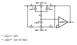
Thank you, John. What would you think of something like this circuit, with an extra opamp in front of it (as a non-inverting buffer)?
Let's say we want to have 20db boost or cut of HF and LF, center frequency somewhere between 1kHz and 3kHz, the shelving frequency a reasonable choice that's up to you. Total gain of the circuit at your choice from x1 to x4.
Output impedance of the source around 10k, and the tone circuit is expected to work into a load of 10k too.
Let's limit it to OPA134 and the LME49710 for now. Which one would lead to a nicer overall design?
P.S. You don't have to use the C values indicated in the schematic. They are up to you too.
Attachments
Last edited:
The second application where I believe JFETs are useful is right after the RCA jack on the audio input. The low input bias current of a JFET input lets you use high resistor values after an AC coupling capacitor, decreasing the necessary value of the coupling capacitor. JFETs also have the useful benefit of being more resistant the EMI/RFI effects.
I really loathe low impedance things that force you to use some 100uF or larger electrolytic for coupling....
Thank you, John. What would you think of something like this circuit, with an extra opamp in front of it (as a non-inverting buffer)?
Let's say we want to have 20db boost or cut of HF and LF, center frequency somewhere between 1kHz and 3kHz, the shelving frequency a reasonable choice that's up to you. Total gain of the circuit at your choice from x1 to x4.
Output impedance of the source around 10k, and the tone circuit is expected to work into a load of 10k too.
Let's limit it to OPA134 and the LME49710 for now. Which one would lead to a nicer overall design?
P.S. You don't have to use the C values indicated in the schematic. They are up to you too.
Kind of a broad question there, and since it's Saturday morning and I'm lazy, I'll just venture that my gut says I could build a lower noise version of that circuit with the LME49710, and I always consider lower noise "nicer" 🙂
I really loathe low impedance things that force you to use some 100uF or larger electrolytic for coupling....
There are other solutions than just using the brute force 100uF approach. But they require additional passives and sometimes its nice just to toss down the JFET-input device and move on.
Gents, after 121 pages, can someone answer this simple question - which is better, OPA134 or LME49710 ?
I like my own bicycle best.
- Status
- Not open for further replies.
- Home
- General Interest
- Everything Else
- What is wrong with op-amps?