I’ve read another thread and got your point, Greg.
But I think OPA637 and three pairs of output FETS, er, slightly expensive.
Had you used stacked supply for diff pairs and VAS?
Any buffer between VAS and OS?
No cascode in diff stage, yes?
Keep it simple and let NFB to do the job?
But I think OPA637 and three pairs of output FETS, er, slightly expensive.
Had you used stacked supply for diff pairs and VAS?
Any buffer between VAS and OS?
No cascode in diff stage, yes?
Keep it simple and let NFB to do the job?
Hi Dimitri,
Yes I guess a bit hard on the wallet. I'm not sure what you're referring to with OPA637 and 3 pairs of output FETS - a 200W+ power amp?
Had you used stacked supply for diff pairs and VAS?
???
Any buffer between VAS and OS?
No
No cascode in diff stage, yes?
No
Keep it simple and let NFB to do the job?
absolutely
I mean higher voltage clean rails for diff pairs and VAS to achieve full output swing.Had you used stacked supply for diff pairs and VAS? ???
Regarding sound quality and distortion figures...
I would tend to agree that the THD figure (as in x%) does not correlate well with percieved sound quality. It is after all based on excess harmonics produced out of one sinewave stimulus, but this holds true for standard published figures. Let me give an example:
0.1% THD at 1kHz 1W sets one single point in a multidimensional continuum of sorts - if you compare percieved sound quality from many amps where measurement gives you that same figure, you will get amps that differ like night and day. That ONE single point gives you little usable data. That being said, it is quite likely that an amp with 100 times less THD under the same conditions, may sound better. And this is really all one can say with any accuracy if one is fixated to one single point of measurement.
Things however change drastically once you start showing distortion spectra, preferably in relation to output power an/or frequency - not to mention intermodulation sweeps etc - correlations between measurements and perception become more evident, though not obvious or absolute. As one poster mentioned, if you cannot measure a difference between amps that sound different, then either your hearing is deceiving you, or more likely, you are using the wrong instruments to measure the wrong things. When this leads to avoiding to admit ones own ignorance by dispensing the dogma that all measurement (or for that matter all listening) is worthess, well... it's called the height of arrogance, to put it mildly.
Still, determining one-point-of-measurement THD from listening tests is as futile as going the other way around. Music is a vector sum of, for all intents and purposes, infinite sinewaves, all of which generate different spectra of harmonics - some of which may reinforce, and some of whic may cancel - and that's excluding IM and TIM effects. Just like measurements need to be speciffically targetted to reveal a problem, so muct material in listeming tests. But unless you find correlation between the two, you are flying blind. Designing amplifiers is as much an art as it is science, but one cannot function without the other in this endevour - overemphasizing one over the other is a path to at best mediocre products if not downright abominations.
ilimzn: I think that is a very good way of putting it. This is an ancient discussion, between the theoretic and 'artform' school of amplifier designing. It must exist in 100's of threads here on diyaudio.com 😉
I was just trying to place 'guru' in either of the two schools.
I was just trying to place 'guru' in either of the two schools.
some things that are related to the thread...
I don't think so that PCB lay outs can affect so much on sound
quality, for as long as you are not designing a PCB layout
that is a 100 square in. in area
this will only be very true when you are designing amps
for the Radio Frequency spectrum as such that you would always see to it that you are always keeping the standing wave raito low.
most audio hobby kit websites put this to emphassy that one contribution
to a good sounding amp is a better PCB layout. "their" PCB
lay out. very commercial......

best regards,
hienrich
I don't think so that PCB lay outs can affect so much on sound
quality, for as long as you are not designing a PCB layout
that is a 100 square in. in area
this will only be very true when you are designing amps
for the Radio Frequency spectrum as such that you would always see to it that you are always keeping the standing wave raito low.
most audio hobby kit websites put this to emphassy that one contribution
to a good sounding amp is a better PCB layout. "their" PCB
lay out. very commercial......
best regards,
hienrich
hienrich said:
I don't think so that PCB lay outs can affect so much on sound quality, for as long as you are not designing a PCB layout that is a 100 square in. in area
this will only be very true when you are designing amps
for the Radio Frequency spectrum as such that you would always see to it that you are always keeping the standing wave raito low.
most audio hobby kit websites put this to emphassy that one contribution to a good sounding amp is a better PCB layout. "their" PCB lay out. very commercial......
best regards,
hienrich
Heinrich, you would probably be surprised how wrong your supposition that PCB layout does not affect sound is. I have seen some quite ingenious PCBs as well as others that could be mercifully described as 'attempts' - both on the DIY and commercial side of the fence, including makers of kits. If there is one area where design resembles artform,. that would be PCB design. Improper routing of power and ground lines, or even signal lines in high impedance circuits can reduce even the best topology to literally an interference generator. That being said, once you get to a certain level of competence, as with anything, there is a law of diminishing returns at work. Still, when you are aiming at superlatives, all stops need to be traken out, and that includes VERY careful PCB design.
ilimzn said:Heinrich, you would probably be surprised how wrong your supposition that PCB layout does not affect sound is.
I would go so far as to say that the PCB is an integral part of
the design, and I can introduce or cancel all sorts of effects
through design alone.
As exhibit A, I point to the classic HK Citation 12 which had a
a trace routing which by itself introduced a 2nd harmonic. That
part of the circuit board was altered on the Mosfet Citation 12.
We don't doubt about your knowledges, Nelson. 😎 But I many time asked personaly, why are you making amps, which have not so low distortion. 😎
And I reply again: I like very simple amps with low
feedback.
Your statement presumes that I have not or do not
offer amplifiers with low distortion figures. Much
most of what I do is well less than .1% at ordinary levels
and frequencies and some of it is less than .01%.
feedback.
Your statement presumes that I have not or do not
offer amplifiers with low distortion figures. Much
most of what I do is well less than .1% at ordinary levels
and frequencies and some of it is less than .01%.
 . You don't ?
Yes dimitri re your post 103,
I would consider winding a few extra turns onto a stoch toroid to get a rectified, low current 10V DC and tack it on as a regulated 5V to run the Vas up above the output supply for that few extra watts of output OR experiment with n output stage with gain in which the Vgs is not a limitation. They're often more complex to obtain low distortion and stability under reactive loading.
Ilimzn,
Agree wholeheartedly. 0.1% second harmonic is innocuous while 0.1% of crossover notch which goes up at lower levels or output commutation spray of harmonics are much less palatable.
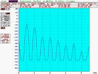
Given that many of the nastier distortions are generated in response to higher power signals in the mid ranges but emanate from our tweeters with lower levels of signal information giving spatial detail is, I believe, why such detail information is easily buried/masked in hash/noise. While crossover notches are fairly easily tamed and don't get worse with higher level, the output commutation n harmonics spray, as seen in my thumbnail (posted again here) in response to a pure sinewave signal and intruding through the PSRR or induction, GOES UP WITH POWER.
heinrich,
I've already related my experience while working for a well known US manufacturer where the designer was testing a new design (actually a rework of someone elses old design - maybe John Curl's) where the main Vas output track had been routed around the differential inputs and back again by the PCB drafter. The unit tested 0.3% THD at 1KHz and the engineer was scratching his head. I spotted it, suggested he cut it and run a jumper away from the input and the THD dropped 2 orders of magnitude. "I didn't know layout mattered" was his response. Of course, confronted with this revelation he asked me for guidance in attacking the issue scientifically.
I proceeded to identify the tracks carrying nasty supply commutation artefacts, the functional blocks with high currents and low level, high impedance blocks. He then sawed a board up into little pieces, joined them up with 4"-6" jumpers, fired it up and started moving them around in 3D space while watching the THD analyser - until it went up in flames and had to hit it with a fire extinguisher!!!! What a mess.
Hello Nelson,
Of course you can tune you're harmonics with layout. But when it's the output stage commutation harmonic spray you just don't wan't it in there! Your approach, correct me if I'm mistaken, is to run Class A so they don't exist. Too easy. Mine is to confront the beast and render it innocuous at low cost by careful layout and design for high PSRR. Feedback is one of the tools I use. Feedback is my friend. I have converted many low feedback designs for great audible improvement - in fact I did this with the Magnet 200W/ch amp that became their flagship with the remote control folded cascode preamp in 95.
I'm working on a very low cost design (initially 150W/8 ohm) and targetting 0.001% at 20KHz at full power, low bias AB. The goal here is to have such a low masking effect that more detail, spatial information, and no doubt recording flaws are exposed. WARTS and all if you like. All while averaging less power consumption than a 60W light bulb, environmentally friendly***** rating.
I would consider winding a few extra turns onto a stoch toroid to get a rectified, low current 10V DC and tack it on as a regulated 5V to run the Vas up above the output supply for that few extra watts of output OR experiment with n output stage with gain in which the Vgs is not a limitation. They're often more complex to obtain low distortion and stability under reactive loading.
Ilimzn,
Agree wholeheartedly. 0.1% second harmonic is innocuous while 0.1% of crossover notch which goes up at lower levels or output commutation spray of harmonics are much less palatable.
Given that many of the nastier distortions are generated in response to higher power signals in the mid ranges but emanate from our tweeters with lower levels of signal information giving spatial detail is, I believe, why such detail information is easily buried/masked in hash/noise. While crossover notches are fairly easily tamed and don't get worse with higher level, the output commutation n harmonics spray, as seen in my thumbnail (posted again here) in response to a pure sinewave signal and intruding through the PSRR or induction, GOES UP WITH POWER.
heinrich,
I've already related my experience while working for a well known US manufacturer where the designer was testing a new design (actually a rework of someone elses old design - maybe John Curl's) where the main Vas output track had been routed around the differential inputs and back again by the PCB drafter. The unit tested 0.3% THD at 1KHz and the engineer was scratching his head. I spotted it, suggested he cut it and run a jumper away from the input and the THD dropped 2 orders of magnitude. "I didn't know layout mattered" was his response. Of course, confronted with this revelation he asked me for guidance in attacking the issue scientifically.
I proceeded to identify the tracks carrying nasty supply commutation artefacts, the functional blocks with high currents and low level, high impedance blocks. He then sawed a board up into little pieces, joined them up with 4"-6" jumpers, fired it up and started moving them around in 3D space while watching the THD analyser - until it went up in flames and had to hit it with a fire extinguisher!!!! What a mess.
Hello Nelson,
Of course you can tune you're harmonics with layout. But when it's the output stage commutation harmonic spray you just don't wan't it in there! Your approach, correct me if I'm mistaken, is to run Class A so they don't exist. Too easy. Mine is to confront the beast and render it innocuous at low cost by careful layout and design for high PSRR. Feedback is one of the tools I use. Feedback is my friend. I have converted many low feedback designs for great audible improvement - in fact I did this with the Magnet 200W/ch amp that became their flagship with the remote control folded cascode preamp in 95.
I'm working on a very low cost design (initially 150W/8 ohm) and targetting 0.001% at 20KHz at full power, low bias AB. The goal here is to have such a low masking effect that more detail, spatial information, and no doubt recording flaws are exposed. WARTS and all if you like. All while averaging less power consumption than a 60W light bulb, environmentally friendly***** rating.
i might not have experience this one yet on PCB lay outs
but well of course i do believe that
jumpers and sometimes hard wiring is prone to such problems
not only seen on scopes but could be even heard
through a humming, or even through noise.
best regards,
hienrich
but well of course i do believe that
jumpers and sometimes hard wiring is prone to such problems
not only seen on scopes but could be even heard
through a humming, or even through noise.
best regards,
hienrich
Hi A.G.
What's the dB reference of this display? Is this dBV, or something else? And what is the power level of the 1 kHz output, and the load impedance?
Thanks
What's the dB reference of this display? Is this dBV, or something else? And what is the power level of the 1 kHz output, and the load impedance?
Thanks
to guru:
may I ask if what topologies are you using for the
input and the VAS stages in your designs ?
for me I like those mirror image topologies.
best regards,
hienrich
may I ask if what topologies are you using for the
input and the VAS stages in your designs ?
for me I like those mirror image topologies.
best regards,
hienrich
Hi Andy c,
Don't read too much into it - it was done as a simple lash up, the conditions weren't detailed. It's simply the FFT of a half sinewave, I created by running an amplifier output sinewave through a diode.
If you put a resistor into either the upper or lower supply line feed to your output stage and drove an 8 ohm load with a 1K sinewave you would get a spray of harmonics according to the fourier series -
f(t) = A/pi + A/2sinwt - 2A/pi[1/3cos2wt+1/15cos4wt+.....]
actually all the even harmonics decreasing out to infinity . The higher ones can be easily re-emphasized into the amplifier by a falling PSRR characteristic as frequency increases, typical of so many IC opamps.
I about to give the instrument to my daughters high school as it low res by today's standards.
heinrick,
Yes complementary diff'l pairs followed by a complementary push pull Vas works well, is easily stabilised without resorting to miller Cdom degradation and can use boosted supplies or output gain stage. it will have plenty gain for one loop and low THD. The SE output of the diff'l stages is the weakness for PSRR and complexity follows.
You can introduce some euphonic common mode 2nd HD by having low tail resistances, say running from a 15V zener feed. This is outside the feedback loop and thus not controlled.
is it wise to include current mirrors in the complementary input stage?
I've never done this yet.
some of G. Randy Slone's amps in his book incorporates
current mirrrors in his complementry input stage,
but until then I'm not yet convinced with this approach not unless
if someone else can also prove that this also technically provides
better response and better THD figures. well, of course neglecting
expences.
hienrich
If this is to be the front end of your amplifier, have you considered using complementary JFETs and a cascode to raise their output impedance to improve PSRR especially if you want to use a mirror. Complexity arises but no tail current sources. The current mirror will raise the loop gain at low frequencies and can reduce THD at low frequencies but I doubt it will much change the GBW defined by the Vas and outputs.
Try both for twice the fun. See if you can discern the difference. You need to have upstream transparency to do definitive aural evaluation.
Try both for twice the fun. See if you can discern the difference. You need to have upstream transparency to do definitive aural evaluation.
- Status
- Not open for further replies.
- Home
- Amplifiers
- Solid State
- What every Class AB builder needs to be constantly aware of