
Ah, you've managed to conflate the discussion from plastic coating to plastic components. And, yet again, use it for another opportunity to have a dig at anything British.But it seems British, Aston Martin put plastic brake pedals, had to recall when they broke.
Yawn.
A quick search reveals :-
https://www.slashgear.com/aston-mar...call-after-finding-pedals-could-snap-05315770
"Chinese subcontractors revealed it had been using a fake plastic to the DuPont material the car firm had specified."
I'm sure Aston Martin would not of had the problem if they had sourced the pedals from a supplier based in India..... and using plastics manufactered from oil imported from your number 1 supplier and best mate?
Fiat 1100, blimey, I've never heard of or ever seen one. So relavent. Let alone one made in India. How quaint.
🤣
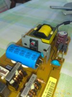
The Nippon KZH was always there? Because I wouldn't expect to see it on an SMPS that also uses a Lelon main capacitor. On the other hand it has a blue marker pen dot that looks like a factory check off. The Lelon REA has a blue dash mark.I last repair my Sony Blue Ray player.
Two parallel sotky rectifier diodes in 12v circuit.One of each was sorted.
D201.
Aston Martin annual sales are about 6,400 units.
6400 brake pedals, at a 1 minute cycle time, are about 4.5 days production on an injection molding machine.
Insignificant, and I for one would not deal with a fussy customer offering a cut throat price that makes me compromise on quality.
I would expect a set of employees to inspect all incoming bought out items, both at the contractor / supplier level, and factory inward warehouse.
Ultimately, the company's reputation has suffered because of this incident.
The report in a plastics trade journal ('Plastics Today') said the material was recycled, but chemically identical to the specified one, cause was low price offered to the actual maker in China, by the supplier who sold the item to Aston Martin. He was left with no choice but to use cheaper, and weaker raw material, which was not inspected before fitting on the cars.
Caterham sells less than 700 cars annually, with 123 employees as per the latest information on the net, they currently use Ford engines.
As such, not a very significant operation.
The reason for applying a bottom coat on a vehicle is to protect the metal from corrosion, and also abrasion / impact damage from sand and stone chips mixed with water thrown by the tires onto the bottom part of the vehicle.
If it works there, the item is of use in weather proofing metal articles used outdoors, including garden gates for example.
Last edited:
For those who do not follow the news about these subjects:
Lotus Cars and Volvo are majority owned by the Chinese Geely Group.
Caterham is finally owned by the Tune Group, based in Malaysia.
Aston Martin is also currently owned by overseas investors:
https://en.wikipedia.org/wiki/Aston_Martin
Reason for posting is that progress, and time, does change a lot of things.
Last edited:
Yes,the only part that i have replaced are two diodes,D201,D202.The Nippon KZH was always there? Because I wouldn't expect to see it on an SMPS that also uses a Lelon main capacitor. On the other hand it has a blue marker pen dot that looks like a factory check off. The Lelon REA has a blue dash mark.
Big disappointment 😔 from this Sony player.
I have bought a long time ago,never used not in main connected,just dust collector.
Yesterday i have tried to use and this was death.
Electrolytic capacitors deformed due to have not seen voltage for years in that Sony and they acted up ugly on first power on as it seems.
A hint on how to slowly energize SMPS capacitors after a long storage would be useful.
Variac works on transformer based supplies, here in SMPS the controller would try to correct the output.
Variac works on transformer based supplies, here in SMPS the controller would try to correct the output.
Variac would not apply in this occasion. Only if taken out and reformed. Maybe a dim bulb tester could have saved the initial surge though.


Do you have any images of the bottom of your st-35. I would like to change the cable on mine. Put in an earthed oneA Dynaco ST35. Really a no-brainer, a quad of well matched EL84 , a new power cord and a real cable lock
and it is singing
6,400 units, yes, but they are very nice units. Have you driven one or something similar? Could you afford one?Aston Martin annual sales are about 6,400 units.
6400 brake pedals, at a 1 minute cycle time, are about 4.5 days production on an injection molding machine.
Single impression, twin would be mechanically better. Why do you assume single impression? Clue, low cost suppliers again 😉
You appear to have some knowledge of injection moulding, perhaps you could enlighten us further with your expertise?
Namaste.
I designed a model railway DCC booster.
It used mosfet gate drivers to drive a mosfet H bridge.
Quite simple and worked great.
However gate drivers were becoming expensive to acquire.
On one of my other projects I used motor driver IC which is very cheap.
So I replaced mosfet gate drivers with the motor driver IC.
Got pcb back today and built one up.
Powered it up and just got a flashing error LED.
Looked at power supply and SMPS output was bouncing up and down to a couple of volts before resetting.
I looked up schematic and everything looked fine.
Couldnt see anything wrong on the pcb, no shorts. missed joints etc.
It really should have just worked.
It took a good while to work it out but motor driver IC isnt a straight H bridge.
If inputs are both zero the output is floating which turned on both mosfets in h bridge and shorted out supply.
I looked at a hardware fix then realised I could fix it in software.
If input is 00 then I output 11 instead. Fixed it a treat.
Last edited:
Recently fixed a lcd monitor whose backlight was working but no picture. After some troubleshooting found out power was not getting into lvds connector. Traced and found that buck converter chip was bust. Could not find chip easily available. Googled the specs of converter and found an alternative thats available for almost free(mp2307) and pin compatible. Fixed! That was so satisfying.
A hint on how to slowly energize SMPS capacitors after a long storage would be useful.
Variac works on transformer based supplies, here in SMPS the controller would try to correct the output.
I've just reformed some linear PSU capacitors using a 10k 5w resistor in series with a variable power supply and just slowly increased the voltage until they are at their maximum rated volts. Discharged and repeated a few times over a week. These are a pair of those large (22,000uF) Nichicon caps from an old 70's amp I'm going to use in a low cost project where ultimate performance isn't that important and failure can be tolerated.

When I've replaced elements I've found they are accessible from the front (stick your head in the oven 😉) after removing an internal rear panel in the oven cavity that is over the element and fan. Usually enough free wire to pull through and get hold off.
Today, BassFace DB2.1s a car amplifier with quite a bad reputation. But in my opinion, at least this particular model does not look bad at all structurally. If the parts were of better quality, it would be a OK amplifier.
5 out of 8 power supply converter MOSFETs are faulty, considering this amplifier and its power, I replaced them with higher quality SUP60N06-18 and 4 in use instead of 8. Manufacturer had originally used STP65NF06, but as mentioned, 5 of them were faulty and 3 are fully functional, however, their measurement gave conflicting results. Capacitance above 8nF although the manufacturer's data sheet gives this value as 1.7nF.
Can't imagine what MOSFETs are used in this fake batch.
SUP60N06-18 gives a corresponding value of about 2.2nF when measured, but this difference from data sheet is due to the difference in measurement mode, how the manufacturer get this lower value.
Unfortunately, there was nothing else wrong with this amplifier and after replacing MOSFETs it came alive, boring to repair.
Next is Italian garbage on corner of my table - a Parsek MarkBass Little mark III bass guitar amplifier with a strange anomaly in form of grid humming noise.
Considering price of this amplifier, it is unbelievable what kind of crap it is made of. An IR21531D fluorescent lamp ballast driven to very last limit of its switching frequency driving big, sleepy MOSFETs...this is what its power supply looks like.
It will be interesting to dissect it.
Not in the Bosch series 8... it's screwed in through the wall from the back. You need access to remove those two screws that hold the element itself. Some awesome forward support planning from development engineering there.When I've replaced elements I've found they are accessible from the front (stick your head in the oven 😉) after removing an internal rear panel in the oven cavity that is over the element and fan. Usually enough free wire to pull through and get hold off.
- Home
- Member Areas
- The Lounge
- What did you last repair?