Thanks!!! I am really happy with how it turned out.
What I can do is share a very 'quick' plan of pieces. It's not that complicated. A few cuts and bends, with sizes in both inches and mms. Would that be of any help? Interestingly enough, it fits the PCB in both orientations, so there is a certain versatility to how people could build the project.
But, since the DIY Audio Store is soon to release a case done specifically for the WHAMMY, maybe this is all a moot point. Still, my offer of sending blue prints still stands if anyone is interested.
Thanks again,
Rafa.
Last edited:
It’s each board parallel together and one board becomes a left channel and other board becomes a right channel with only one output used per channel ? Or is the circuitry not modified and each board is used as a left and right channel with the other channel in each board remaining unused ? I know there is a version of the headphone amplifier which I have DarkVoice 336 where they use to independent circuits of the 336 combined them together in one chassis with independent volume pots on left and right channel and I think that was called the DarkVoice 337 or 339 can’t quite remember
These two boards are totally independent.
If you use them for Balanced/Symmetric, left boards' two channels amplifying +/- of a balanced signal.
It is the same for right board, for the right channel's +/- balanced signal.
If you use it as a balanced headphone amp, it needs independent floating connections for left/right transducer.
I don't know, was I understandable?
Regards,
Gyuri
answer to Gyuri
Hello Gyuri,
this is what I thought. For me absolutely understandable.
And a very cool solution!!! I also like your solid case.
Your project gave me a cooking 'brain-soup' for a while. 😀
The opto-bias of the whammy -output adjusts for super low offset
and gives you a nice balance between + and - to ground - driven symmetrical?
Really fantastic!
Greets Dirk
Thanks!!! I am really happy with how it turned out.
What I can do is share a very 'quick' plan of pieces. It's not that complicated. A few cuts and bends, with sizes in both inches and mms. Would that be of any help? Interestingly enough, it fits the PCB in both orientations, so there is a certain versatility to how people could build the project.
But, since the DIY Audio Store is soon to release a case done specifically for the WHAMMY, maybe this is all a moot point. Still, my offer of sending blue prints still stands if anyone is interested.
Thanks again,
Rafa.
Rafa,
That would be great. Thanks. You have done a great job with that case..
My sources mostly have balanced outputs, with studio levels.
MSB Platinum Link DAC has 7.5V RMS, for example.
So I don't need so much voltage gain what WHAMMY has.
What is the best way to reduce WHAMMYs voltage gain?
I have 50K ALPS pot on WHAMMYs input.
I would like to thanks for any advice!
Except for that:
You can lower output level in digital domain.
😉
MSB Platinum Link DAC has 7.5V RMS, for example.
So I don't need so much voltage gain what WHAMMY has.
What is the best way to reduce WHAMMYs voltage gain?
I have 50K ALPS pot on WHAMMYs input.
I would like to thanks for any advice!
Except for that:
You can lower output level in digital domain.
😉
The amp has a global feedback loop to reduce the open loop gain of the opamp. It should be quite easy to lower the gain by applying more NFB (change value of R8 and R4 to a lower value I guess).
ratio of R8/R12 and R4/R1
alter R8 and R4
take care of stability (cap across if needed)
all ref. to sch in post #1
alter R8 and R4
take care of stability (cap across if needed)
all ref. to sch in post #1
Thanks.
I thought something similar.
But I need some confirmation.
Anyway, I think I might be a bit uncertain.
Or maybe not?
I thought something similar.
But I need some confirmation.
Anyway, I think I might be a bit uncertain.
Or maybe not?
You can lower output level in digital domain.
😉
But doing that throws away bits, which are information. I'd rather have the volume knob not turned up much, than throw away music.
Lowering gain as you plan is a good approach.
Since the gain is fairly low due to lots of feedback a bit more shouldn't change it much. But you would be best to try it.
lowering the Level in the digital domain is never a good idea 🙂 all digital volume Levels should allways be at max.
grounding question
I've had to redo a number of things but am getting pretty close to finishing my WHAMMY preamp. Before I go further, I thought I might avoid some more desoldering by asking for some advice.
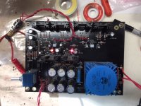
I have connected both my input and output RCA grounds to the same buss bar that includes the orange capacitor. Is this ok, or am I creating a problem by doing so. I think the attached picture shows pretty clearly what, Ive done.
I've had to redo a number of things but am getting pretty close to finishing my WHAMMY preamp. Before I go further, I thought I might avoid some more desoldering by asking for some advice.
I have connected both my input and output RCA grounds to the same buss bar that includes the orange capacitor. Is this ok, or am I creating a problem by doing so. I think the attached picture shows pretty clearly what, Ive done.
Attachments
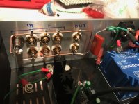
I thought of that myself, and took another route: I made sure that only the input audio ground is connected to the earth ground through to the CAP. The outputs use the audio ground from the PCB and are isolated from the chassis.
What strikes me as odd is that you have not connected the chassis to the AC earth, but directly the earth ground through the cap to the audio ground.
Therefore, you don't have a grounded chassis. I would not like to have that in my setup. As per the guide, i would try to connect that third leg to the chassis, and the audio ground through the cap to it.
Also, what is the leftmost input connector? It appears that its ground is directly coupled to the chassis, and that would 'bypass' the cap for all audio ground once you get that third leg connected to the chassis.
That is what I can pick up from my very limited knowledge. I may be completely mistaken, so take my observations with a grain of salt!
Nice build!
Rafa.
Last edited:
Rafa,
Thanks for helping out. You can't see in the photo, but the chassis is also grounded to AC earth. There's a lead from earth side of the capacitor to one of the bolts holding the AC terminal to the back plate. All the chassis plates will be connected to ground by leads going to the bolts that hold the pcb to the bottom plate. A star ground I guess. The bottom plate will be tied to the back plate so that it is connected to AC ground.
Is there a reason to ground the output to the Audio ground? Is it because the input ground signal causes noise in the output, when connected to the same ground? I dont think I fully understand the difference between the audio ground and the AC ground. Isn't everything eventually going to the AC ground?
I can easily modify what I've done to tie the output ground to the audio ground, just curious about the reasoning, I need to understand grounding better. I've found it a bigger challenge than building the PCB.
By the way, your build was really nice looking, especially the chassis, it's very cleanly executed. Ive been flailing around with the chassis and hookup for weeks, some early versions were lessons in what not to do. I had to scrap my first front and back plates, which I had already had engraved : (
Thanks, Jim
Rafa, the jack to the far left is an 1/8 inch auxilliary jack, I can see now that the phone jack shell ground also grounds to chassis, so will create a ground loop. I'm going to replace with RCA jacks and use an adapter cord for iphone and ipod input.
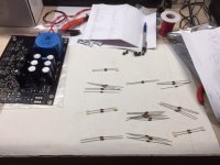
Hey, All. I just put this thing together based on the parts kit I got a few weeks ago. I got the email to comment about the kit, but hadn't put it together yet, so I thought I'd show up here now and log my feedback...
It was an afternoon and a morning to assemble it. I didn't have any issues, everything worked out first time. 14 ma DC on each channel. The voltage regs heat up to ~125 F pretty quick, the other power devices are cooler 90 to 95 F. Sound is quite nice, I don't have much listening on it yet having just sound through it an hour or two ago. I get a bit of buzz when I touch the volume shaft.
When I got the kit, the leads on my power transformer were a bit bent up. It would be nice if that shipped with a bit of protection there.
Looking through the instructions, the LED voltage reference setup (which I executed) is mentioned on the schematic (@ beginning of thread and included in the kit) as omitting R9 and R13. R10 and R14 also appear to be omitted.
C20 - the actual device that shipped to me was a blue rectangle. It didn't seem to give any hint as to what kind of device it was or what value it had. Eventually I figured out it was the only thing that had lead spacing to fit in the C20 spot, but I stared at the thing for a while, wondering what it was.
Hey, could I get a bit more info about C2 and C7? Just curious, and I'm more on the speaker builder side than the amp builder, myself. In what case would you want to populate these?
I read this whole thread a fair bit ago, but haven't kept up with it, so apologies if I'm just popping in with redundant questions / info.
Thanks to DIYAudio for putting the kit together! I bought the circuit board earlier, but wasn't looking forward to sorting out the BOM to actually assemble. This was quite convenient.
Next is get a case, and consider if I want to try and get a stepped attenuator.
🙂
Attachments
- Home
- Amplifiers
- Pass Labs
- "WHAMMY" Pass DIY headphone amp guide