The coupling caps are optional if your source components have low offset and especially if you use fet opamps. Measure it and see if you can live with it.
The coupling caps are optional if your source components have low offset and especially if you use fet opamps. Measure it and see if you can live with it.
Thanks! I'd rather try to live with no caps. After trying different caps in my SET amps and heard such differences, I realized it only adds coloration and it's always a compromise.
It's fun to come back from vacation and see everyone's progress! I was especially excited to see Rafa's build because I read his original posts in November when he was ordering his parts.
This evening I finally had a chance to return to my broken build (https://www.diyaudio.com/forums/pas...s-diy-headphone-amp-guide-83.html#post5619174). In December, @MEPER suggested that I should:
"First step is to check the power supply to see if you have the correct +- rail voltages. It is like going through 6L6's steps again. Then you can check opamp and measure voltage over gate stoppers, check bias etc....."
I've completed the first step, and the rail voltages are both correct.
For the next steps, I'm not quite sure how to proceed. Does anyone know how to safely check the opamp and measure voltage over gate stoppers and check the bias? Any help would be greatly appreciated! I'll also see if I can glean anything by reading the build post again and searching on YouTube.
A few additional observations in case they're meaningful:
1. The LED at D5 only turns off faster when headphones are connected.
2. I'm seeing 15V between R17/R27 and circuit ground. I think that's the output voltage of the opamp?
3. At the headphone output, I'm seeing about 12 mV (not sure if that's + or -). This doesn't change when I adjust the volume knob.
From R17 and R27 to ground I would expect about 0V.
The opamp should have -15 VDC at pin 4 and +15 VDC at pin 8 when looking at the schematic. Since you measure +15 VDC at opamp output there is something wrong. Maybe a problem with the -15 VDC to the opamp?
Maybe also check that opamp is oriented the correct way in the socket (not turned 180 degree). I have no idea if this would result in +15 VDC at output.
From R17 and R27 to ground I would expect about 0V.
The opamp should have -15 VDC at pin 4 and +15 VDC at pin 8 when looking at the schematic. Since you measure +15 VDC at opamp output there is something wrong. Maybe a problem with the -15 VDC to the opamp?
 The hills are live with the sound of muuuuusic!
Thank you @MEPER, this was very helpful! The opamp was receiving about 16.8 and -16.5 on pin 4 and 8. Not exactly 15, but hopefully that's within the normal range?
This made me think that perhaps I managed to fry the opamp somehow. Maybe when I was using the hacksaw to cut out a piece of the board it generated a large amount of static? I had an extra TI opamp in a box, and after I replaced that part I heard music again! It's unfortunate that I destroyed my fancy $7 Analog Devices opamp, but I'm relieved to have a working WHAMMY again.
I hear a loud hum, but now I'll put everything back into the chassis and test it again.
Thank you, @6L6, that's good to know. I am using the LEDs.
Now I'm trying to diagnose the hum. It's still there after putting everything in the chassis, and I noticed that I'm getting only music in the right ear and only the hum in the left. The hum is completely gone when the volume knob is at zero, and it gets very loud as I turn up the volume.
Now I'm trying to diagnose the hum. It's still there after putting everything in the chassis, and I noticed that I'm getting only music in the right ear and only the hum in the left. The hum is completely gone when the volume knob is at zero, and it gets very loud as I turn up the volume.
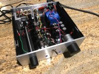
Completed-but noisy
After many hours working out the hookup wiring and layout, I'm almost finished with my pre-amp build. I've found that preamps require a lot more knowledge of grounding and are very susceptible to picking up stray noise. I could use assistance in sorting out my noise issues as I'm new to this, and have a lot to learn.
The board is a standard build with one of the recommended op-amps, I don't remember which one offhand. It powers up fine and produces good gain in both channels. But, I am getting pretty strong 30hz hum (measured with my phone's strobe tuner app) in the input channels that have any source connected to them, whether sending a signal or not. For instance an RCA adapter and aux cord produce little or no 30hz noise, however when the phone is connected the 30 hz starts. When the phones is unpluged the AC hum disappears or diminishes greatly after a second or two delay. As well, I get radio noise from input channels that are connected to something, the radio noise ramps up sharply in the last few steps from wide open on the volume control.
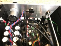
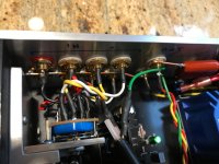
I am guessing I have not properly handled grounding or have left too much untwisted wiring at the input selector switch. It is quite difficult to solder all the connections and leave only a little bit of wiring left untwisted, what you see in the photo is about the best I could do, with the 18ga stranded wire I used for hooking these up. I suspect a lighter gauge might be easier but I'd be surprised if it the difference would be significant. Channels with nothing connected are silent, there can be some bleed of radio noise from an adjacent connected channel (crosstalk?).
That there is no noise from the fifth position of the selector switch which is not utilized at all leads me to believe the problem lies upstream of the selector switch.
The grounding is handled as follows:
-Input grounds are tied to the safety ground via a .47uF capacitor.
-Chassis is grounded to the safety ground via a lead from the AC input terminal screw to the AC input ground terminal. The sides of the chassis are tied together either by sanding the anodizing (or paint) and using a star washer to connect the panels, or by tying together with wiring.
-Output terminals are grounded with a common wire to audio ground on the board.
-Input cable sheilding is tied to the audio ground. (Should that go instead to the safety ground or to the input jack ground upstream from the capacitor?)
The only nonstandard part of the board is adding blue LED power indicators on the front panel from R10 and R14.
Finally on a positive note, aside from the noise issues, the preamp sounds good and has slighty better highs and a slightly better defined soundstage, than the Carver CT-7 that I have been using. This is going to a Nirvana Electronics Works A-20 amp driving Shahinian Obelisk speakers. I would recommend a pre-amp project to any newbie as it forces much more careful consideration of layout, wiring and grounding issues. I've found these to be much more challenging than stuffing a through hole circuit board, or following an example that someone has already worked out layout and wiring.
After many hours working out the hookup wiring and layout, I'm almost finished with my pre-amp build. I've found that preamps require a lot more knowledge of grounding and are very susceptible to picking up stray noise. I could use assistance in sorting out my noise issues as I'm new to this, and have a lot to learn.
The board is a standard build with one of the recommended op-amps, I don't remember which one offhand. It powers up fine and produces good gain in both channels. But, I am getting pretty strong 30hz hum (measured with my phone's strobe tuner app) in the input channels that have any source connected to them, whether sending a signal or not. For instance an RCA adapter and aux cord produce little or no 30hz noise, however when the phone is connected the 30 hz starts. When the phones is unpluged the AC hum disappears or diminishes greatly after a second or two delay. As well, I get radio noise from input channels that are connected to something, the radio noise ramps up sharply in the last few steps from wide open on the volume control.
I am guessing I have not properly handled grounding or have left too much untwisted wiring at the input selector switch. It is quite difficult to solder all the connections and leave only a little bit of wiring left untwisted, what you see in the photo is about the best I could do, with the 18ga stranded wire I used for hooking these up. I suspect a lighter gauge might be easier but I'd be surprised if it the difference would be significant. Channels with nothing connected are silent, there can be some bleed of radio noise from an adjacent connected channel (crosstalk?).
That there is no noise from the fifth position of the selector switch which is not utilized at all leads me to believe the problem lies upstream of the selector switch.
The grounding is handled as follows:
-Input grounds are tied to the safety ground via a .47uF capacitor.
-Chassis is grounded to the safety ground via a lead from the AC input terminal screw to the AC input ground terminal. The sides of the chassis are tied together either by sanding the anodizing (or paint) and using a star washer to connect the panels, or by tying together with wiring.
-Output terminals are grounded with a common wire to audio ground on the board.
-Input cable sheilding is tied to the audio ground. (Should that go instead to the safety ground or to the input jack ground upstream from the capacitor?)
The only nonstandard part of the board is adding blue LED power indicators on the front panel from R10 and R14.
Finally on a positive note, aside from the noise issues, the preamp sounds good and has slighty better highs and a slightly better defined soundstage, than the Carver CT-7 that I have been using. This is going to a Nirvana Electronics Works A-20 amp driving Shahinian Obelisk speakers. I would recommend a pre-amp project to any newbie as it forces much more careful consideration of layout, wiring and grounding issues. I've found these to be much more challenging than stuffing a through hole circuit board, or following an example that someone has already worked out layout and wiring.
Attachments

As I'm working to troubleshoot the noise in the left channel, I've discovered two more things:
1. The noise is mostly high frequency, with peaks at around 2khz and 12khz, and a dip at around 6khz.
2. The noise doesn't change when I unplug the cable that was plugged into the left RCA input.
1. The noise is mostly high frequency, with peaks at around 2khz and 12khz, and a dip at around 6khz.
2. The noise doesn't change when I unplug the cable that was plugged into the left RCA input.
You're so far off stock at this point that you need to be sure wat you think works actually works...
First, disconnect all the input/output wiring from the Whammy and use one set of inputs directly to the PCB's input, and wire the headphone jack, and make sure the Whammy first and foremost works as designed.
With that verified we can continue forward, without knowing that it's all just shoveling sand into the tide. 🙂 We'll get it figured out. 😀
.
.
That there is no noise from the fifth position of the selector switch which is not utilized at all leads me to believe the problem lies upstream of the selector switch.
The grounding is handled as follows:
-Input grounds are tied to the safety ground via a .47uF capacitor.
-Chassis is grounded to the safety ground via a lead from the AC input terminal screw to the AC input ground terminal. The sides of the chassis are tied together either by sanding the anodizing (or paint) and using a star washer to connect the panels, or by tying together with wiring.
-Output terminals are grounded with a common wire to audio ground on the board.
-Input cable sheilding is tied to the audio ground. (Should that go instead to the safety ground or to the input jack ground upstream from the capacitor?)
.
.
It is not quite clear from this what exactly is your audio ground. I guess maybe the input ground, which is lifted from chassis/safety ground via the .47uF cap?
If so, then it is incorrect to connect the input shielding to that. It should be connected directly to chassis/safety ground. However, this would also depend on how the source component is wired to prevent a ground loop through the cable shielding.
I’ll try 6L6’s suggestion to use one input to check the function of the PCB . First I’ll relocate the input shield to the safety ground to see what effect that has. That will be really easy, and I would like to try one change at a time. To answer Henryve, the audio ground is the output ground pad on the PCB, the GND halfway between left out and right out.
Then again, scrap what I said about shield. I was thinking of XLR connections. My mind not yet in gear for new year. 
FET Opamps
Wayne,
I have low DC offset from my DAC so I tried the Whammy without input caps and it certainly sounds a little different. I need to do some comparison listening tests to see if I think it sounds better.
What is it about FET opamps that makes them sound better without input caps ?
Which of the opamps 'recommended' for the Whammy are 'FET' ?
Thanks
Mark
The coupling caps are optional if your source components have low offset and especially if you use fet opamps. Measure it and see if you can live with it.
Wayne,
I have low DC offset from my DAC so I tried the Whammy without input caps and it certainly sounds a little different. I need to do some comparison listening tests to see if I think it sounds better.
What is it about FET opamps that makes them sound better without input caps ?
Which of the opamps 'recommended' for the Whammy are 'FET' ?
Thanks
Mark
Hi like to ask for a bit of Whammy op amp suitability guidance?
I was looking at an ebay listing for a HDAM full discrete dual op amp and thought it might be suitable to try in the Whammy but not really to sure spec wise.
Here is the description.
HDAM full discrete dual op amp based on Marantz HDAM circuit model, use of FET input precision pairing warmest sound, pin familiar with fully compatible NE5532 MUS02 OPA2604 LME49720HA and other op amp
Op Amp Features:
1 it is not necessary that the depth of the op amp negative feedback, more natural sound
2 op-amp power supply may be higher, up to + -28V can work, more dynamic (under + -9V even good job)
3 higher output current, general op amp output current within about 40MA, this op amp maximum output current of 100MA
Package Included:
1 x Full Discrete DUAL Channels Op Amp Module replace NE5532 MUS02 OPA2604 LME49720
Full Discrete DUAL Channels Op Amp Module replace NE5532 MUS02 OPA2604 LME49720 | eBay
Sure, try it!
I'd suggest making the 2 electrolytic capacitors closest to the socket lay down out of the way, or use a smaller cap, 10uF 25v is more than sufficient in that position, in order to make some room for the assembly.
I'd suggest making the 2 electrolytic capacitors closest to the socket lay down out of the way, or use a smaller cap, 10uF 25v is more than sufficient in that position, in order to make some room for the assembly.
Super thanks Wayne just ordered one to try.
The 25v caps either side of the op amps I have laid over all ready but as you mention 10uf 25v would work ok as a replacement and as I happen to have a bunch of small flat mkp film ones that I would be able to squeeze in on the underside of my board would this be worth doing in place of the electrolytics I have Silmic's in at them at the moment would also do C9 as well?
I was also thinking of trying this with C12, C17, C22, C25 paralleling up two of the 10uf for 20uf in place of the 22uf electrolytic?
Cheers
Jamie
- Home
- Amplifiers
- Pass Labs
- "WHAMMY" Pass DIY headphone amp guide