👍The resistors should be rated 3W for 5,1 Ohm, the simplest wirewound or ceramic resistors are perfect here (they add some inductance, which is a good thing). There's absolutely no need at all to get fancy parts and/or tight tolerances here.
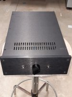
Long before the store had the Whammy boards, member Meldano made his own boards (I think it was still called the Pass HA at that stage). I bought one, including his universal psu, in January 2017. Today I finally finished it 
First tests are that it sounds very relaxed, completely different from the scaled down Aleph I recently (finally) completed. So, now my wife has 2 headphone amps to choose from (until I finish another oldie, the Juma headamp; probably similar vintage) 😎
For what it's worth, my build used:
First tests are that it sounds very relaxed, completely different from the scaled down Aleph I recently (finally) completed. So, now my wife has 2 headphone amps to choose from (until I finish another oldie, the Juma headamp; probably similar vintage) 😎
For what it's worth, my build used:
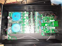
- Meldano's psu, so dual mono
- OPA627 opamps
- 313/2013 Mosfets
- Muse ES bipolar 22uF capacitors
- Alps RK27 50k
- 1uF polypropylene input capacitor
- high biased (120mA) output stage (R16, R22, R29 & R32 4R7)
Attachments
Last edited:

Hello guys,
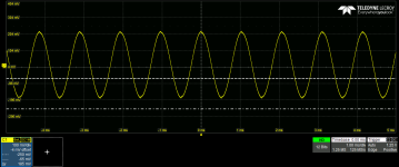
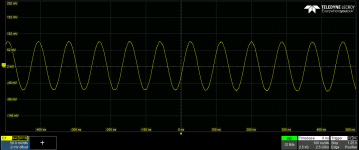
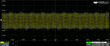
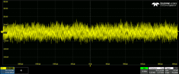
I switched on the amp for the first time and I watched the output signal with a scope. Unfortunately I see some oscillation over the signal.
C2 and C7 are mounted and they are 100 pF. and the OpAmp is OPA2134. If I change the opamp and I use a LME49720 the signal is even worse and the output oscillates even without an input signal. I tested the amp without a load. The input signal is 1 kHz and it seems to be good on the pcb test point.
Please any idea?
Thanks!
Attachments
Hi,
can you post the noise output when you connect a shunter RCA plug on the inputs? (signal and sig ground connected together)?
do you have the same figures on both channels?
OPA2134PA should work perfectly, I have it in mine. LME49720 (which I also have tested in this amp) has a much higher BW, so it could explain why there are even more oscillations.
Are you using the officiel PCB and parts or did you add some modifications?
Cheers
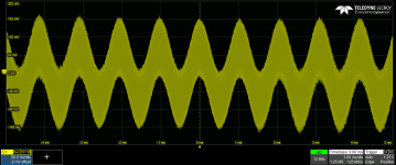
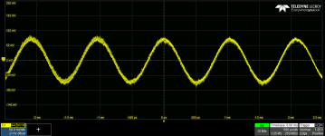
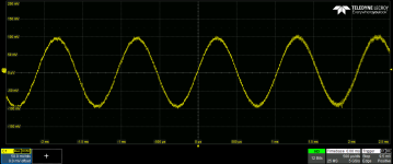
ok..tested with a 32 ohm load and it is better, I doesn't oscillate anymore, but still the signal is not clear, there is a modulation over the signal
Attachments
Thank you Denis, I'm using the official PCB and parts, tomorrow I will take the signal with shunted inputsHi,
can you post the noise output when you connect a shunter RCA plug on the inputs? (signal and sig ground connected together)?
do you have the same figures on both channels?
OPA2134PA should work perfectly, I have it in mine. LME49720 (which I also have tested in this amp) has a much higher BW, so it could explain why there are even more oscillations.
Are you using the officiel PCB and parts or did you add some modifications?
Cheers
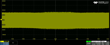
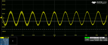
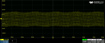
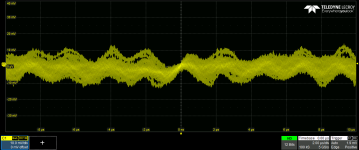
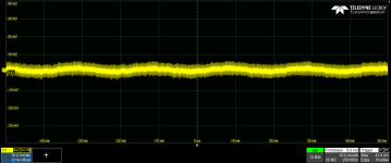
noise output with shunted RCA inputs. Both channels are the same.
Attachments
Last edited:
Which MOSFETs are in the output stage? My WHAMMMY (the third M is for Mutant) shows good results with the IRF parts.same channel, both shunted, different horizontal scale
If it's any help, I bypassed C3 and C4 with a couple of 10 uF 50V ceramics that were looking for an excuse.
Also, if you followed the power supply instructions to the letter, the rails will be +-18v, if not more, so your opamp may have a short life.
which regulator version did you build? LED reference, resistors or shunt-based?
If you built the recommended red LED version of the regs, the rails should be at +-17V or even a tiny bit less (but for sure not 18V or more), which is perfectly safe for both OPA2134 and LME49720.if you followed the power supply instructions to the letter, the rails will be +-18v
Yes, both channels show the same result.
I'm using the "naked" regulators and the output voltages are +- 15 V. The MOSFETS are FQP3N30/FQP3P20. I'm trying to understand if the noise comes from the power supply or it's picked up from some other reason
I'm using the "naked" regulators and the output voltages are +- 15 V. The MOSFETS are FQP3N30/FQP3P20. I'm trying to understand if the noise comes from the power supply or it's picked up from some other reason
even though the LED version is the quietest of all, I don't expect the naked regs to be the cause of so much noise. What resistors are you using in the CRCRC of the power supply filters? what is the input voltage of the regs?
The yellow LED version approaches +-18v. Even +-17v is uncomfortably close to the "never exceed" rating of 2134 or 49720, and I prefer better margins in my circuits.
Just for grins & giggles, have you tried disconnecting the RCA and shorting the input to ground at the junction of C1 and R2?
Just for grins & giggles, have you tried disconnecting the RCA and shorting the input to ground at the junction of C1 and R2?
Scrape the paint from all contact areas, to ensure good EMC. Especially where the potentiometer mounts the front panel. Keep the IEC ground lead short and thick, use braided wire.
We might be able to see the obvious... if you cared to post a photo or 2, together with the CRO shots.
We might be able to see the obvious... if you cared to post a photo or 2, together with the CRO shots.
The output is likely a 1/4" stereo jack. If so, what happens if it's taken out of the chassis and hanging in the air? I wonder whether a funky ground might be causing issues.
That's why it's best to stick to red LEDs for the 2134 or 49720: the voltage is always kept below +-17V, giving you some safety margin for the 2134. Imeasured mine again, the voltage at the output of the regs is +-16,8V , giving you a total of 33,6V. At the Opamp, the Voltage had droped another +-0,1V, so it runs at 33,4V. Way below the 36V absolute max voltage rating.The yellow LED version approaches +-18v. Even +-17v is uncomfortably close to the "never exceed" rating of 2134 or 49720, and I prefer better margins in my circuits.
Apart from very specific Opamps, I don't see the point of using yellow leds, especially with the opamps mentioned above.
The resistor version is a bit noisier than the led version, but still.
As mentioned by Extreme_Boky and DSP_Geek, yes, proper grounding is key. Also, how are your chassis and signal ground connected to earth?
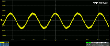
I think the noise it's just picked up from the probe. Connecting the output to the scope with a 50 ohm cable is much better. Also the amplitude of the signal wasn't very high. The ripple at the output of the power supply seems to be acceptable.
Anyway.. I think that a 12-bit oscilloscope can show you more than you can hear... With headphones I don't hear any noise at all and the sound of the ampli is very good!
Anyway.. I think that a 12-bit oscilloscope can show you more than you can hear... With headphones I don't hear any noise at all and the sound of the ampli is very good!
Attachments
- Home
- Amplifiers
- Pass Labs
- "WHAMMY" Pass DIY headphone amp guide