LM833 DC Offset
Nisbeth
Thanks for your help and the pointer to Tangent’s site for how to deal with ‘cranky’ op amps. The problem is that Post #1 -6 implies that if you use the BOM, schematic and one of the listed op amps then no adjustments, including DC offset, will be required. Having used an LM833 from the listed op amps I was not expecting 24mV DC offset. I didn’t know if the problem was my bad build or the op amp.
A list of op amps that deliver < 5mV DC offset using the BOM, pcb, and schematic and a list of (‘cranky’) op amps that are known to have a high DC offset that will need tweaking would therefore be useful at the beginning of this thread.
Most of the DC-offset probably comes from the opamp (due to something called input bias current, as explained here) The LM833 is bipolar input whereas the OP2134 is JFET and as JFET opamps have much lower input bias currents, they also tend to have a much lower output offset.
Your voltages looks spot on to me, so if you are concerned with the offset either switch to a FET-input opamp or consider going through the thread for suggestions on how to trim the output stage to null the offset.
Nisbeth
Thanks for your help and the pointer to Tangent’s site for how to deal with ‘cranky’ op amps. The problem is that Post #1 -6 implies that if you use the BOM, schematic and one of the listed op amps then no adjustments, including DC offset, will be required. Having used an LM833 from the listed op amps I was not expecting 24mV DC offset. I didn’t know if the problem was my bad build or the op amp.
A list of op amps that deliver < 5mV DC offset using the BOM, pcb, and schematic and a list of (‘cranky’) op amps that are known to have a high DC offset that will need tweaking would therefore be useful at the beginning of this thread.
dc offset problem
I think what Wayne is saying is that the input bias current on the LM833 will flow through the 100K resistor on the + input pin. The inputs are PNP as shown on the datasheet so the bias current will flow out of that pin and create a positive offset voltage on the pin. The typical bias current is about 300nA. Flowing through the 100K resistor gives a typical offset of 30mV, which isn't far from the 24mV you measure. You can reduce the input resistor to reduce the offset, change to a different op amp with lower input bias current, or add a DC servo circuit to cancel it out.
I think what Wayne is saying is that the input bias current on the LM833 will flow through the 100K resistor on the + input pin. The inputs are PNP as shown on the datasheet so the bias current will flow out of that pin and create a positive offset voltage on the pin. The typical bias current is about 300nA. Flowing through the 100K resistor gives a typical offset of 30mV, which isn't far from the 24mV you measure. You can reduce the input resistor to reduce the offset, change to a different op amp with lower input bias current, or add a DC servo circuit to cancel it out.
LM833 DC Offset
jhofland
Thanks for that : now I understand what I am aiming for. I am ordering an OPA2134, several more LM833s to see if there is any sample variation, and some trimmers to see if the offset will adjust to zero or a least within a few millivolts.
I think what Wayne is saying is that the input bias current on the LM833 will flow through the 100K resistor on the + input pin. The inputs are PNP as shown on the datasheet so the bias current will flow out of that pin and create a positive offset voltage on the pin. The typical bias current is about 300nA. Flowing through the 100K resistor gives a typical offset of 30mV, which isn't far from the 24mV you measure. You can reduce the input resistor to reduce the offset, change to a different op amp with lower input bias current, or add a DC servo circuit to cancel it out.
jhofland
Thanks for that : now I understand what I am aiming for. I am ordering an OPA2134, several more LM833s to see if there is any sample variation, and some trimmers to see if the offset will adjust to zero or a least within a few millivolts.
fyi if using the slightly larger Aliexpress enclosure there is enough space to try one of those inexpensive ebay stepped attenuators.
Any impressions of the stepped attenuator JaimeMcC? Does it give good range? Any noise pickup?
Works well no noise good range. Just a bit of a hassle having to modify the thick face plate in order to mount it.
Sorry if this is a dumb question but anyone have thoughts on what might be a good way to reduce DC voltage at C1 & C5 to 0 (if achievable) I am curious to see how the Whammy would sound without these capacitors in the signal path capacitors?
I am not 100% sure if my interpretation is correct on this or if so how safe this is to do.
I am not 100% sure if my interpretation is correct on this or if so how safe this is to do.
It certainly is doable to eliminate the input coupling caps C1 and C5 IF (caps intentional) you are confident that there is no DC component to the input signal. Any DC offset will be present at the output.
Currently I measure 0.04mV and 0.02mV would this be considered low enough to be no DC component if not what might I try to reduce this to zero?
Note this was with headphones plugged in and music playing measured with a UNI-T UT61E on the C1 and C5 lead outs.
Note this was with headphones plugged in and music playing measured with a UNI-T UT61E on the C1 and C5 lead outs.
Last edited:
OK removed C1 & C5 mV on the jumpers similar DC offsets 0.04mV and 0.02mV this improves depending on what I use for a ground.
On the headphone out jack dc offset hovers around 2mV and 3mv with my meter (this is lower than I had previously measured roughly a week ago)
Checked out with my cheap testing headphones then switched over to my HD800 nice result.
Super thank you for the guidance.
On the headphone out jack dc offset hovers around 2mV and 3mv with my meter (this is lower than I had previously measured roughly a week ago)
Checked out with my cheap testing headphones then switched over to my HD800 nice result.
Super thank you for the guidance.
Sorry if this is a dumb question but anyone have thoughts on what might be a good way to reduce DC voltage at C1 & C5 to 0 (if achievable) I am curious to see how the Whammy would sound without these capacitors in the signal path capacitors?
I am not 100% sure if my interpretation is correct on this or if so how safe this is to do.
JamieMcC
Apologies for the late response and if I am 'teaching my grandmother', but there's a good summary of the pros and cons of taking out input caps here :
Input Capacitors for Headphone Amps
Tangent's explanations are always good 🙂
Just one comment that as far as I recall the electrolytics in the feedback path (C26/C27) means that the Whammy has G = 1 for DC, meaning that DC from the source would be passed through if you do not use input caps, but it would not be amplified by the Whammy.
Just one comment that as far as I recall the electrolytics in the feedback path (C26/C27) means that the Whammy has G = 1 for DC, meaning that DC from the source would be passed through if you do not use input caps, but it would not be amplified by the Whammy.
Thanks for the guidance and links guys very much appreciated I will be sure to check my offsets on the whammy for the different sources I use as well.
Last edited:
I have a couple of questions:
Does anyone know when the PCBs will be back in stock in the diyAudio Store?
What exactly is the purpose of R39/R40? The schematic shows that they along with the volume pot forming some type of voltage divider influencing the gain in some way.
In a early post I read where Jim stated that they "have all to do with oscillations" or something along those lines.
I just don't understand why they're needed.
Thanks.
Help !
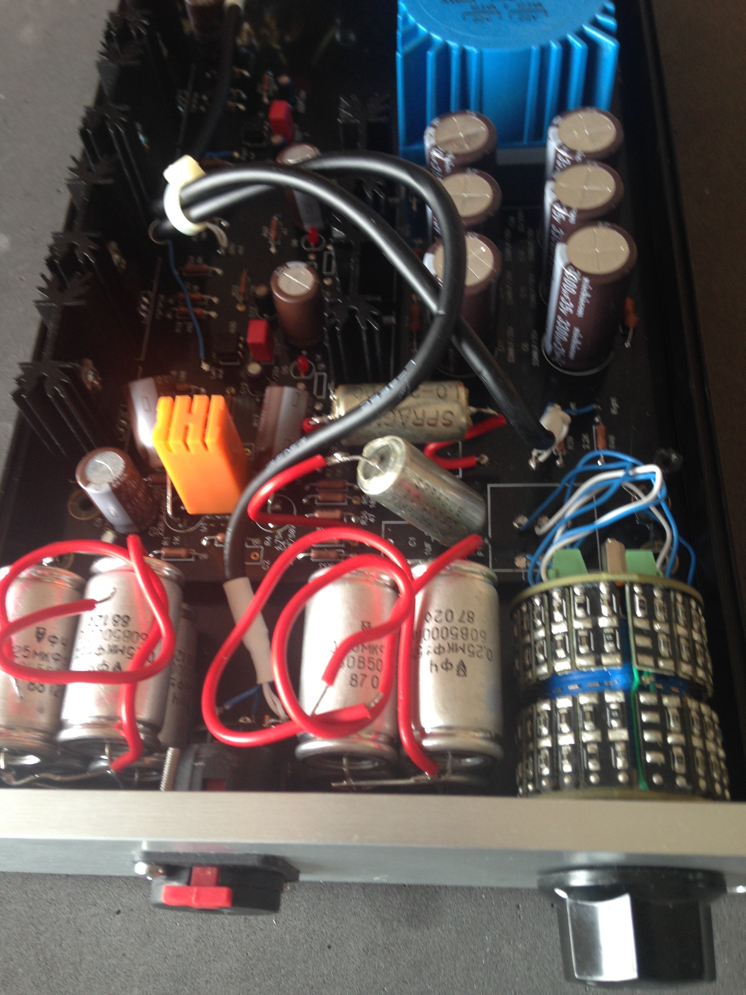
While working on my Whammy I shorted something(s). I thought I had blown the regulators and the LEDs were off. I have replaced the regulators but the LEDs are still not on, and I am getting 30V on the regulator outputs and the opamp power pins. Can anyone point me to the best places to troubleshoot the problem ?
While working on my Whammy I shorted something(s). I thought I had blown the regulators and the LEDs were off. I have replaced the regulators but the LEDs are still not on, and I am getting 30V on the regulator outputs and the opamp power pins. Can anyone point me to the best places to troubleshoot the problem ?
- Home
- Amplifiers
- Pass Labs
- "WHAMMY" Pass DIY headphone amp guide