Its a nice enclosure I was very happy with it but be aware the aluminium face plate is quiet thick which might be a problem if mounting hardware to it. The threaded part of my Alps volume pot would not go all the way through as is and I had to make a recess on the back of the face plate for the pot to sit in so the threaded part would poke though enough to get the nut on to secure it.
1706 all aluminum amplifier chassis / preamplifier case / DAC / AMP Enclosure / case / DIY box (172*60*251mm)-in Amplifier from Consumer Electronics on Aliexpress.com | Alibaba Group

1706 all aluminum amplifier chassis / preamplifier case / DAC / AMP Enclosure / case / DIY box (172*60*251mm)-in Amplifier from Consumer Electronics on Aliexpress.com | Alibaba Group
Last edited:
Case
Jamie McC
Thanks for the heads up. I have an ALps Blue pot. Measuring it from the flat front of the pot casting to the end of the thread gives 6mm. The front is supposed to be 8mm thick. It looks like I need to counterbore the spindle hole to fit the c. 13mm boss on the casting to give about 2mm of thread out the front for the fixing nut. Is that what you did ? Did you use a flat bottom milling tool, or did a drill bit suffice to counter bore the spindle hole ?
Some Questions
6L6/Wayne
I built my Whammy yesterday and it's sounding good. I have some questions about it :
- I am getting about 24mV DC offset at the headphone socket under load. Voltages at the regulator are -16.77V and -16.74V. Is the DC offset normal ? (I am worried about my 35 ohm Fidelio headphones !)
- I was getting some 50Hz mains hum until I connected the IEC mains socket earth pin to one of the input phono socket earths per the photos at the beginning of this thread. Now it's just a faint hum between tracks. I couldn't find this documented anywhere in the build instructions. There is also an orange capacitor in the earth line in the photo. What type and value is the capacitor and what does it do ? Is there a better place to connect the pcb star earth ?
Apologies if one or both of these questions has already dealt with in this thread.
I am planning to build a pair of MoFo as well.If you choose the BA-3 or Whammy you will have enough output swing to drive an F4 or MoFo.
If I want to use WHAMMY as preamp to drive MoFo. Is there anything need to adjust, say gain value or something else?
I am planning to build a pair of MoFo as well.
If I want to use WHAMMY as preamp to drive MoFo. Is there anything need to adjust, say gain value or something else?
The default gain has worked successfully, depending on the op amp you would choose, you can work on the transformer/linear chips combo....I used OPA2134, so used a 0-18 V transformer with 7818/7819 pair
Adding EQ to Whammy
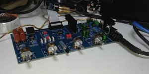
I started my Whammy experience by ordering a PCB from the DIYAudio store. I built it up exact to spec. And I really liked it! Kudos to you Wayne for such an elegant design.
Being so happy with the headphone amp I decided to experiment with Whammy as a line level preamplifier. I transferred Whammy to a PCB layout of my own making and added my favorite rendition of baxandall tone controls. I added a switch to bypass the EQ from the signal. I moved the power supply off board and was able to shrink the PCB to 100mm x 217mm.
I am very happy with the results and will continue with my experimentation.
Attachments
Jamie McC
Thanks for the heads up. I have an ALps Blue pot. Measuring it from the flat front of the pot casting to the end of the thread gives 6mm. The front is supposed to be 8mm thick. It looks like I need to counterbore the spindle hole to fit the c. 13mm boss on the casting to give about 2mm of thread out the front for the fixing nut. Is that what you did ? Did you use a flat bottom milling tool, or did a drill bit suffice to counter bore the spindle hole ?
I used a normal flat bit in pillar drill with a little Boelube lubricant to make the recess for the alps pot
ps I used a 0.22uF 250V Metallised Polyester Film Capacitor connected to the rca's and no noise at all
Last edited:
Nice to see the builds progressing along. I appreciate the thanks and am working on something for this year.


I am getting my BOM together to build a Whammy and have a couple of power supply questions.
The BOM in post 1 lists a transformer part number of 6663 or 6664, the board artwork lists 6363 or 6364. Looking at the Amgis web site, 6663 and 6664 are not listed, so I assume they are typos.
I believe the 6363 is 2X15V and the 6364 is 2X18V and the Amveco 70053 is 2X22V, the Amgis 6365 is 2X22V. If I have relatively easy to drive headphones, will the 6363 be the correct choice? I’m planning to use the LED biasing scheme.
I assume that if I want to drive more difficult headphones or even small speakers with this, I should build with the 2X22V transformer and tweak the gain resistors when I upgrade the ‘phones, even though the 2X22V transformer will run the regulators hotter, using the same LED biasing setup. Sound like a plan? If not, any alternative suggestions?
Thank You,
Rob
The PCB pattern is for the 15 or 25 VA transformer either will fit. I built with the 22 Volt because I had them but 15 is just great for headphones and you get a little less heat.
Can't wait to see what you're working on Wayne 😀Nice to see the builds progressing along. I appreciate the thanks and am working on something for this year.
Carl the preamp board looks great! Nice job 🙂
I have just ordered my PCB, is there a BOM for this or will I have to go through all the posts to get the info?
The PCB pattern is for the 15 or 25 VA transformer either will fit. I built with the 22 Volt because I had them but 15 is just great for headphones and you get a little less heat.
Wayne, Thank you for the help and the design.
If you don't mind, I'm going to dig up some things from my AC circuits class that was required in school, even though I'm a mechanical engineer.
In the power supply, the voltage out of a bridge is 1.4X the voltage input. I think we can assume that there is sufficient capacitance to use this value at the output of the filter cap bank. So we get 1.4X15V = 21V into the regulator, which is set to 15 + 1.8 (LED)=16.8V feeding the outputs. Ignoring the limits of the output transistors, for right now, the 15V transformer will provide enough voltage to keep the system fed since 21V > 16.8V.
If we up the transformer to 18V and keep the regulator the same, we get 1.4X18V=25.2, which seems to me to be also sufficient, but would cause greater heat dissipation in the regulator, since our output is still the same.
I guess the real question is: Given equal availability and cost, is there any reason to go with a transformer greater than 15V? Which leads to a related question: If there is a desire run the output devices at a higher voltage by changing the regulator circuit, how much and by which method would be preferred to do so? Post #2 lists several methods of setting the regulator output voltage with multiple voltages listed.
Thank you for any answer you have. I'm going to try and understand the output device data sheet. 😱
Rob
- Home
- Amplifiers
- Pass Labs
- "WHAMMY" Pass DIY headphone amp guide