to dparkes #4180
Hello dparkes,
your safety earth (at the IEC-inlet) has to be connected directly to the case of your WHAMMY. No caps or whatever inbetween. Try to keep it short. Safety first!
What you have seen on pics is a connection from 'audio-ground' (RCA-ground) to 'earth/safety-ground' via a cap as a groundloopbreaker.
Cheers
Dirk 😉
Thank you for this reply.
One follow up question, if I may. The kit I received also does not have a place for the safety earth bolt on the back panel next to the power inlet. What are folks doing for the safety earth in this instance? I know there's a orange cap that supposed to connect to this from the RCA's, yes?
Thanks again.
On my kit, the bottom panel has a separate hole for the ground connection.
Thank you for this reply.
One follow up question, if I may. The kit I received also does not have a place for the safety earth bolt on the back panel next to the power inlet. What are folks doing for the safety earth in this instance? I know there's a orange cap that supposed to connect to this from the RCA's, yes?
Thanks again.
You're welcome 🙂
I think the other guys have answered the earthing question. The connection has to be able to carry the fault current in the even of a short from live to case until the fuse blows.
The connection has to be to bare metal, if it is anodised or painted then it won't do. Also all parts of the case should be earth bonded meaning that other panels of the case (top, front etc) must also be in direct electrical contact with each other and ultimately with the ground connection.
Smell, almost smoke, power resistor overheat.
Request help from forum before giving up. Have build 10+. Can provide picture but that's unlikely helping.
1. Assemble power section, everything works ok. LED config, red. +- 16.86V at measure points.
2. Stuff rest of the PCB and connected IO.
3. Upon power on, small came in a few seconds, all 4 power resistor (5.1 Ohm) went beyond 180C with in 10 seconds. 30 seconds result in solder start melting on the resistors (happened during the first time power on - was checking where the smells came from.
----
Diag:
1. Disconnect all IO - did not help.
2. Double checked both opto, the 6 heats devices, no shorting points. Meter used.
3. Resolder all points that only one side of the PCB has solder dome.
4. Measure transformer both primary VDC 122.8, both secondary VDC 18.07.
5. Rechecked polarity of all capacitors, looks good.
6. Voltage drop on all 4 power resistors are 5.44-5.46V.
One point to note - 220 uF capacity came with the kit were 4 50VDC, and 2 25V VDC. Based on measurement 25v VDC is OK.
Symptom remain the same. 2 power head sink are 45-55C (normal).
6 Power capacitors are at 60-70C (being heated by the resistors).
Dare not leave them on over 15 seconds (180C resistors)
Any suggestions for me to further diagnose?
Thanks a lot.
Lots of possibilities.
First step is switch off and check for obvious short across each rail on the amp. Measure resistance directly across C9 and C28.
If there is a short then you need to investigate.
I would have thought the 10 ohm resistors on FET's would get hot if there was an issue with amp itself but you need to check. If you short out C13 and C23 you force zero bias.
Do the 5.1 ohm resistors still burn?
If they do then just gently lift one leg of each 10 ohm to isolate the FET's and retest.
Do they still burn?
Thanks a lot, Mooly.
I was able to find it out in a hard way. I start to desolder the parts off - a group at a time -
pot,
C1/5,
Q3-Q6, and found that Q3-6 was the problem.
I assumed they are the same, but they are actually two pairs 610 and 7610, it's shame.
Then I recall a very minor brightness difference on the two red LEDs, very minor, and my meter can tell different at 0.02V.
Fixed and soldered things back. No sound, both channels.
Further trouble shooting:
Both 4N35 provide same reading at no load (good sign, albeit no reference).
OmAMP have +16.84 - 16.84v on pin 1 and 8. Pin 3 has +0.08v but pin 6 is zero (expect -0.08 if pin3 is correct).
Interesting part:
When the AMP is powered off:
Output GND, output L, output R are disconnected.
When AMP is powered on
Output GND, output L, output R are shorted (all three together)
Tested connectivity based on schema - they are all connected.
Albeit I am not able to explain it clearly, I suspect I shorted some PCB trace.
Will get a PCB, and do the rework when I have more time.
Smell, almost smoke, power resistor overheat.
Request help from forum before giving up. Have build 10+. Can provide picture but that's unlikely helping.
1. Assemble power section, everything works ok. LED config, red. +- 16.86V at measure points.
2. Stuff rest of the PCB and connected IO.
3. Upon power on, small came in a few seconds, all 4 power resistor (5.1 Ohm) went beyond 180C with in 10 seconds. 30 seconds result in solder start melting on the resistors (happened during the first time power on - was checking where the smells came from.
----
Diag:
1. Disconnect all IO - did not help.
2. Double checked both opto, the 6 heats devices, no shorting points. Meter used.
3. Resolder all points that only one side of the PCB has solder dome.
4. Measure transformer both primary VDC 122.8, both secondary VDC 18.07.
5. Rechecked polarity of all capacitors, looks good.
6. Voltage drop on all 4 power resistors are 5.44-5.46V.
One point to note - 220 uF capacity came with the kit were 4 50VDC, and 2 25V VDC. Based on measurement 25v VDC is OK.
Symptom remain the same. 2 power head sink are 45-55C (normal).
6 Power capacitors are at 60-70C (being heated by the resistors).
Dare not leave them on over 15 seconds (180C resistors)
Any suggestions for me to further diagnose?
Thanks a lot.
Lots of possibilities.
First step is switch off and check for obvious short across each rail on the amp. Measure resistance directly across C9 and C28.
If there is a short then you need to investigate.
I would have thought the 10 ohm resistors on FET's would get hot if there was an issue with amp itself but you need to check. If you short out C13 and C23 you force zero bias.
Do the 5.1 ohm resistors still burn?
If they do then just gently lift one leg of each 10 ohm to isolate the FET's and retest.
Do they still burn?
You sound to have a lot going on there 🙂 So a problem with the FET types.
Resistance readings on a DVM will not be reliable if there is any power applied. Even tiny voltage differences between points being measured will give a non valid result.
The opto isolator can be linked out for test purposes. Just short out the 0.1uF cap across pins 4 and 5. You will have no bias current but it should otherwise work OK.
Hello,
I am building the audio store kit and the four 5.1R power resistors were not included. I have 4.7R on hand. Would I be ok substituting those?
Thanks,
Alan
I am building the audio store kit and the four 5.1R power resistors were not included. I have 4.7R on hand. Would I be ok substituting those?
Thanks,
Alan
Hello,
I am building the audio store kit and the four 5.1R power resistors were not included. I have 4.7R on hand. Would I be ok substituting those?
Thanks,
Alan
yes, perfectly fine.
You sound to have a lot going on there 🙂 So a problem with the FET types.
Resistance readings on a DVM will not be reliable if there is any power applied. Even tiny voltage differences between points being measured will give a non valid result.
The opto isolator can be linked out for test purposes. Just short out the 0.1uF cap across pins 4 and 5. You will have no bias current but it should otherwise work OK.
I am settled. Thanks again. I used wrong side pin from the audio jack connector. Did not realize the insert - disconnect mechanism in the kit connector (checked my ACP+ and realized it...)
This kit came raw (1 bag of J/FET, 1 bag of OpAmp + 4N35, everyone else in one big bag). No packing list (matched to BoM and schema). Replaced power caps (blue vishay) and input coupler caps (grey film Vishay BC). From my understanding, the key of design is to provide a very clean power source in 3 levels and the rest is a straight forward amp.
If I am only using 25, 40 and 42 Ohm headphones is there any problem using using +/-18V or even +/-15V supplies? Will this cause any degradation? (Only using low impedance headphones? I assume +/- 21.5V is the normal target.) With how the bias is set perhaps nothing needs to be changed?
Next, if I have LM317/LM337 supplies that I am happy with (built with good quality components & capacitors) is there any reason for me not to layout a WHAMMY HPA board without a built-in power supply? I assume not.
I ask because I just loaded up KiCad after ordering the HPA-1 boards and I was thinking of starting a WHAMMY layout (no on-board power supply) as a next project to start on.
Low impedance headphones are often pretty efficient and so lower supplies are certainly feasible. A scope across the output will show what kind of voltage swing you yourself need.
I did that very test on my headphone amp and found 800 millivolts peak to peak swing on transients was more than enough. I used a single 6.8v rail for comparison 🙂
So -/+ 9 or 12 volt supplies may be fine, perhaps with a tweak of the 10k network around the output stage.
I did that very test on my headphone amp and found 800 millivolts peak to peak swing on transients was more than enough. I used a single 6.8v rail for comparison 🙂
So -/+ 9 or 12 volt supplies may be fine, perhaps with a tweak of the 10k network around the output stage.
For the 10k network perhaps leave the two inner resistors at 10k and then reduce the outer two 10k resistors to maintain the same current through them at the reduced supply voltage? Does that sound like the right direction?
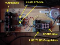
to kozard #4193
Hello kozard,
I did something similar as you describe it. I built a CRCRC-filter followed by
LM317/LM337 regulators (adjustable rail-voltages).
And I used single-OPAmps. But I didn't went much lower with the railvoltages.
Was depending on the max. railvoltages of the OPAmps which were used.
And yes, it doesn't look so nice on the wooden test board.... but it sounds great.
Cheers
Dirk 😀
Attachments
For the 10k network perhaps leave the two inner resistors at 10k and then reduce the outer two 10k resistors to maintain the same current through them at the reduced supply voltage? Does that sound like the right direction?
Perhaps you could do that. I suspect it will be very forgiving and will work just fine over a very wide range actually.
Another possibility is unbalancing the network to force the opamp to sink a negative current and push the opamp output stage toward class A. So that would have the lower 10k as a lower value than the upper.
I would need to try it in a sim to see how it behaved but it could be an interesting possibility. Set it up so the opamp sees say 5 milliamp current flowing into its output pin. So around 0.25 volt across the 47 ohm
I was wondering about that opamp output stage Class A trick for a couple of other designs like the Beyerdynamic A1 and the Graham Slee Solo. I assume the other stages in the opamps are Class A already.
I was also wondering if an inverting opamp stage is a better choice for common mode distortion for many opamp models? At least I read that it makes a big difference for NE5534 and NE5532. I don't know about modern designs like OPA1656 or OPA1612 or OPA2228 (or LM4562).
I was also wondering if an inverting opamp stage is a better choice for common mode distortion for many opamp models? At least I read that it makes a big difference for NE5534 and NE5532. I don't know about modern designs like OPA1656 or OPA1612 or OPA2228 (or LM4562).
Not surprisingly, the people who design and sell opamps are aware of the "output stage class A" trick as well. Have a look at the "Typical Applications Circuit" on the datasheet of the LT1115 opamp. There it is, connected to pin #6.
- Home
- Amplifiers
- Pass Labs
- "WHAMMY" Pass DIY headphone amp guide