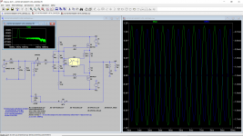
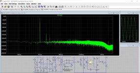
Attached is a quick LTSPICE simulation showing the current (output of the opamp) and the output waveform for a very asymmetric (10k and 3.3k) network.
Is this the right direction for a Class A (opamp output) WHAMMY? "ASYM WHAMMY"?
Or should I go with the LT1115 JFET current sink on the output of the opamp?
Is this the right direction for a Class A (opamp output) WHAMMY? "ASYM WHAMMY"?
Or should I go with the LT1115 JFET current sink on the output of the opamp?
Attachments
That's the kind of thing I meant.
The current in the 47 ohm must always be within the limits of what the chosen opamp can deliver under all signal conditions... so just look at the current in that resistor under full peak to peak swing output swing and make sure its under say 15 milliamps (as a conservative sort of a value, we don't want to push the opamp to hard).
It was just an idea 🙂
Resistor.
The real question (from me, anyway…) is what advantage is the higher current in the opamp going to bring? More linearity? Remember, the output stage is heavily biased class-A, burning up enough current that any change in the opamp current would not be noticed, and that output stage is in the overall feedback loop.
I.E., what’s the point, and what will it gain you?
(Of course, if the answer is “i just want to try it” that is, of course, a completely good reason.)
The idea is to make sure that the opamp output stage is also Class A. The WHAMMY output stage is indeed Class A but what we are talking about is having both the opamp output stage and the WHAMMY output stage both as Class A. As opposed to a Class AB opamp output stage driving a Class A output WHAMMY/MOSFET output stage.
Resistor.
The real question (from me, anyway…) is what advantage is the higher current in the opamp going to bring? More linearity? Remember, the output stage is heavily biased class-A, burning up enough current that any change in the opamp current would not be noticed, and that output stage is in the overall feedback loop.
I.E., what’s the point, and what will it gain you?
(Of course, if the answer is “i just want to try it” that is, of course, a completely good reason.)
I was just thinking outside the box on that one, things to try and experiment with... as you do 😉
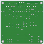
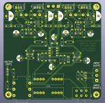
What do you guys think of a Super Shrink WHAMMY PCB that you can order online for $2 at JLCPCB for DIY? (See attached, not finished yet. I would appreciate any suggestions to improve the layout. The back is a ground plane.)
A "WHAMMY For Lean Times" or something like that?
I plan to use it with an existing LM317/LM337 power supply. (I have ones with and without the "LF353 Servo" circuit.)
A "WHAMMY For Lean Times" or something like that?
I plan to use it with an existing LM317/LM337 power supply. (I have ones with and without the "LF353 Servo" circuit.)
Attachments

Class A opamp bias
It is a tweak that ADCOM has used for years in many of their preamp phono stages with an LT1028 (LT1115) like the GFP-565. They use a J555 current regulator diode providing nominal 2 mA current with max spec of 2.6 mA.
Rick
Not surprisingly, the people who design and sell opamps are aware of the "output stage class A" trick as well. Have a look at the "Typical Applications Circuit" on the datasheet of the LT1115 opamp. There it is, connected to pin #6.
It is a tweak that ADCOM has used for years in many of their preamp phono stages with an LT1028 (LT1115) like the GFP-565. They use a J555 current regulator diode providing nominal 2 mA current with max spec of 2.6 mA.
Rick


Neat!! That’s wonderful!
What is the plan for heatsinking? Lay the mosfets on the chassis floor? What potentiometer footprint are you using?
Please include R39 and R40 on the input.
Could you add pads to attach output RCA (fly wired is fine) on the other side of the switching headphone jack? Resistors in series with tip and ring to the RCAs would be handy as well.
Add a few more pads for various size input coupling capacitors.
Yes, the idea is to heat sink on the chassis floor.
I am using the KiCad "Potentiometer_THT😛otentiometer_Alps_RK163_Dual_Horizontal" footprint. I hope that it will also fit the RK27. I need to look into that.
Let me get to work on the other items.
I am using the KiCad "Potentiometer_THT😛otentiometer_Alps_RK163_Dual_Horizontal" footprint. I hope that it will also fit the RK27. I need to look into that.
Let me get to work on the other items.
I assume switch the R & L RCA output but not the RCA ground? There is a switch for the shield but I assume we should leave that unswitched.
Check clearance around input opamp U1. Burson opamp footprint needs 15mm X 13mm for anything taller than the opamp socket. If possible add an optional 0.1uF MKP cap across pins 4 and 8 of U1 to allow implementation of their MKP cap tweek.
Burson Supreme Sound (SS) Opamp 101 Part 1 (MKP cap tweak) - Burson Audio
Burson Supreme Sound (SS) Opamp 101 Part 1 (MKP cap tweak) - Burson Audio
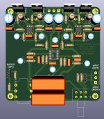
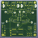
The latest layout and schematic is attached.
I will need to go back and look at the clearance and extra capacitor for the Burson opamp. I just measured 14x16mm for the red plastic case on a V6 Vivid Dual.
With the Burson opamp are you using an extra 8pin machine screw socket to raise the height? I ask since I don't like moving the film bypass capacitors away from the opamp.
Attachments
Wayne's PCB has enough room for Burson if you use smaller diameter electrolytic bypass caps. I added a spacer socket for the MKP cap mod. See post 2911. Here's the link to 2911:
"WHAMMY" Pass DIY headphone amp guide
"WHAMMY" Pass DIY headphone amp guide
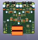
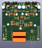
Ok. I added the additional pin 4 to pin 8 film bypass capacitor and moved the bypasses and one resistor a little further out. Burson opamp should fit fine.
New layouts and schematic attached. I welcome all improvement suggestions and error corrections.
New layouts and schematic attached. I welcome all improvement suggestions and error corrections.
Attachments
Among the four M2x daughter cards that use an opamp (Tucson, Norwood, IPS7, Cedarburg), only one of them includes the "opamp output stage class A" trick: IPS7. The output stage current sink of IPS7 is bootstrapped, which is a whole 'nother kettle of fish, neither a resistor nor a JFET. And oh by the way, IPS7 is the M2x daughter card whose sound 6L6 loves the most. Coincidence? Or cause and effect? Decide for yourself.
So I guess the floating or tracking of the opamp supplies to 10V above and below the signal voltage reduces the distortion of the opamp? What else can you tell us about the theory of operation of the IPS7?
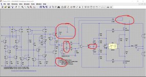
For interest:
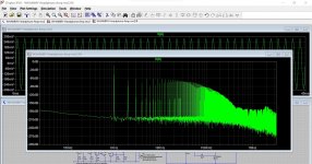
This shows the Whammy with a 'real' opamp, a 741 in this case.
Image #1 is the opamp alone feeding 32 ohm. No Whammy output stage. Note the distortion (as expected).
Image #2 is the same setup but now with a 1k sinking into the opamp output. What a difference that 1k makes at these low levels.
Image #3 is standard Whammy.
Image #4 uses the 1k on the opamp output.
Image #5 is the circuit (attached). Have a play.
Attachments


- Home
- Amplifiers
- Pass Labs
- "WHAMMY" Pass DIY headphone amp guide