there is always enough for the optocoupler to do it’s job and get things set perfectly.
so Wayne practically with two additional resistors nested between gates increased overall current, which is resulting in faster recovery time .......... in ZM layman terms - biasing is tougher
You guys rock. I swear, I've learned more practical stuff here in DIYA than I had in my college engineering courses. Lol
R22 ~~ } without the short-circuit the fluctuations are enormous
R16 ~~ }
That has to be the clue. If you are saying the offset is steady with R5 shorted and all over the place with it not shorted then something has to be wrong around pin 5 and the 100k.
Something is altering pin 5 on its own.
So if you are 100% sure that the problem happens when R5 is not shorted then we look at these:
Possibilities. Try number 2 below first.
1/ Something wrong around C5. This is easy to check . Look at the circuit. If you unsolder and pull up one end of R7 then you isolate everything at the input side. With it isolated the offset should be low and steady.
2/ R5 is damaged and almost open circuit. Easy to check if you remove the IC and then measure the resistance from pin 5 to ground. It should be 100k. Measure from the top of the empty socket to ground to make sure we include the full circuit path.
2/ R5 is damaged and almost open circuit. Easy to check if you remove the IC and then measure the resistance from pin 5 to ground. It should be 100k. Measure from the top of the empty socket to ground to make sure we include the full circuit path.
with the multimeter on 200 kohm I see :
R5 -0.00 I do not know why there is the least ?
I measured the others for information. because R5 does not have a normal measurement I have the impression
R2 118_ 123 117_121
R3 -0.00 117_ 121
R36 -63.5 -63.5
Possibilities. Try number 2 below first.
1/ Something wrong around C5. This is easy to check . Look at the circuit. If you unsolder and pull up one end of R7 then you isolate everything at the input side. With it isolated the offset should be low and steady.
as I realized solution 2 first R5 is also removed from the circuit and therefore an end of R7.
R 32 23_26 mv
R29 23_27 mv
R22 _ nothing
R16 _ nothing
i think i will abandon this project soon, i don't understand why it is not working.😡
Would it help if you understand the very basic opamp theory?
You might be able to sit down and think it through and find where it is falling down.
Just a thought 🙂
You might be able to sit down and think it through and find where it is falling down.
Just a thought 🙂
Would it help if you understand the very basic opamp theory?
You might be able to sit down and think it through and find where it is falling down.
Just a thought 🙂
Ok I'll try.
thank you very much Mooly for your precious help
The rules to remember for opamps are that the output of the opamp will go to whatever voltage is needed to bring the difference in voltage between the two inputs to zero.
Note... when we say 'output' we are going to change that to mean 'the point the feedback is taken from' which is R8.
Don't lose sight of the fact that pin 5 must always be steady and because it is tied to ground via a 100k it will have nearly but not quite zero volts on it.
So what all that means is that with pin 5 at lets say -20 millivolts the end of R8 (the feedback takeoff point) must also assume a voltage of -20 millivolts.
R8 goes to the other input and so if we have -20 millivolts on both then the important difference between the two is zero and it is all correct.
It has to be something really basic amiss with this... work through it slowly and good luck 🙂
How important is the capacitance value of the 0.47uF earth cap?
I have some 0.47uF WIMA caps but only rated at 63V.
I have some 1uF films that are 250V and above, however. Any issue using 1uF instead?
I have some 0.47uF WIMA caps but only rated at 63V.
I have some 1uF films that are 250V and above, however. Any issue using 1uF instead?
^^ Nvm, it seems 63V should be sufficient.
Now that it's all assembled, I'm only getting audio in the left channel. >.<
When I either insert/remove the headphone cable, there's a loud pop in the left channel. The same "pop" occurs a second after when I power off the amp.
At first I thought maybe I had wired the Neutrik switching jack incorrectly, but that wouldn't explain why it "pops" when the amp is powering off tho. Grounding problem?
Hello everybody.
First attempt, however successful, to assemble the PS for "my" WHAMMY.
Economically built with a 2x18v / 35vA transformer, 6600uf filter, LM7815 / 7915.
Not having previously calculated the overall dimensions, that appendix was born.

First attempt, however successful, to assemble the PS for "my" WHAMMY.
Economically built with a 2x18v / 35vA transformer, 6600uf filter, LM7815 / 7915.
Not having previously calculated the overall dimensions, that appendix was born.
Double WHAMMY
Could be a Triple WHAMMY, but I prioritized the two for my brothers first. 🙂
I'm a little bummed that I'm encountering an issue with one of them tho (blue LED).
When the top lid is on, there's a faint buzz. Take the lid off, and it's silent. Do I need to modify the lid to be grounded to the rest of the chassis?
Attachments


So it turned out that one of the amps had each of its panels already making electrical contact to earth.
After manually scraping away the finish in some spots on the buzzing amp, I managed to get it to be just as quiet.
Thanks again Wayne & community! The WHAMMY sounds seriously good.
After manually scraping away the finish in some spots on the buzzing amp, I managed to get it to be just as quiet.
Thanks again Wayne & community! The WHAMMY sounds seriously good.
What regulator are those?
I see that you use the bursons as well 🙂
I personally removed the input caps C1/C5 and still got <0.5mV on outputs with any of my source at any volume.
I did not check but I think the circuit is inherently rejecting DC, no?
Could some expert chime in?
My understanding is that DC has in fact a very low gain due to the 10k resistors between Op amp and output transistor's gate. (I kept C26/C27 in)
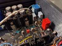
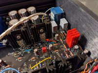
Not familiar (yet) with this project but is it this missing solder OK?
Looks like R7 has one also.
Not familiar (yet) with this project but is it this missing solder OK?
When I learned to solder, I was taught that less is more with solder. Those pieces are soldered underneath the PCB, but I guess I didn't use the same amount for the solder to come through to the other side of the PCB. I also make the components have mechanical contact with the board. Still, I room to improve on my consistency. 🙂
And yeah, you can probably get away with not having those caps. Since these are for my brothers (who aren't OCD audiophiles), I decided it's probably safer to leave them in. I'm considering leaving them out with my own build tho (since I can be aware of it, and measure the gear upstream).
Those are New Class D regs. I'm going to try Sparkos regs on my build.
New Whammy Build Problems
Just finished whammy build using new chassis. Power supply checked out fine 17.5+and - . Im using the 18VA transformer bc the the other ones are sold out. I replaced the 10ohm resistors with 15ohm because pf the transformer change. I used the smaller caps closer to the op amp100 pf 25 volts, but I replaced all the big caps. Was this wrong ? I completed the amp and d5 will not turn on . It starts to turn on with the other led and stops. When I turn the amp off and the other led goes off D5 comes on until , the caps drain. I have no sound , and I was wondering if anybody ahs any ideas regarding troubleshooting?
Thanks
220uf capacitors
I received with my complete kit two 220uf 50v capacitors and two 220uf 25v capacitors, but the PCB board calls for four 220uf 50v capacitors: C3, C4, C9, C28. Am I supposed to use the 25v caps in particular positions?
I received with my complete kit two 220uf 50v capacitors and two 220uf 25v capacitors, but the PCB board calls for four 220uf 50v capacitors: C3, C4, C9, C28. Am I supposed to use the 25v caps in particular positions?
It doesn't matter voltage wise although first thoughts would be to fit the higher voltage cap in positions C9/28 simply because the larger cap probably has a lower E.S.R. however that isn't always the best option directly after a regulator. The 'bigger and better' the cap at a regulator output and the worse its transient performance will be.
Lets say in practice it doesn't matter at all in this case. The non intuitive option is to fit the 50v caps at the opamp if they will fit and not the reg output.
Lets say in practice it doesn't matter at all in this case. The non intuitive option is to fit the 50v caps at the opamp if they will fit and not the reg output.
Safety earth connection
Thank you for this reply.
One follow up question, if I may. The kit I received also does not have a place for the safety earth bolt on the back panel next to the power inlet. What are folks doing for the safety earth in this instance? I know there's a orange cap that supposed to connect to this from the RCA's, yes?
Thanks again.
- Home
- Amplifiers
- Pass Labs
- "WHAMMY" Pass DIY headphone amp guide