(What have you got fitted in the IC socket? It looks strange in a picture)
Now I can't work for the rest.
what do you mean by ic socket ? OPamp ? It's a chinese opamp (aliexpress)
Working from pictures is difficult tbh because I've never seen the real thing, I working of the circuit diagram alone 🙂
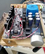
1/ Identify the end of R8 that connects directly to the two 10 ohm resistors. You now unsolder that end to fee it. Just heat the pad and pull the resistor up to isolate that end.
Do not over heat the resistor, be quick. You can also clip a croc clip to the leg to shunt the heat away.
2/ Now identify which end of R17 goes to the two resistors R15 and R23.
3/ Link the end of R17 which you have just identified to the now free end of R8.
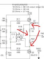
Electrically the circuit should look like this. The voltage on R17 (either end) should be absolutely steady.
(What have you got fitted in the IC socket? It looks strange in a picture)
honestly I don't know if I'll be able to define this on the pcb
Now I can't work for the rest.
what do you mean by ic socket ? OPamp ? It's a chinese opamp (aliexpress)
This is the socket. The opamp is that gold coloured thing you plugged into it. What is it?
Use your meter on a low ohms or diode range to identify continuity between the parts I mentioned. That will tell you what goes where.
Attachments

opamp
It's an aliexpress opamp, I wanted to try a Chinese amp out of curiosity.
Attachments

Thanks for all the suggestions for grounding the Whammy. It really made finishing it properly a whole lot easier.
I have to say it seems to sound better now just because it looks so good. Am I just imagining it? Nah, couldn't be ...
No finished Whammy photos as it looks exactly like the picture in the DIYAudio store.
But there are a couple of pix that are different from other Whammy's (Whammi?). The first one is the wood platform and cardboard front and rear panels that held the Whammy together for almost 3 years. It's not pretty but it did blend in nicely with the ACP+. They were both "open architecture".
The second photo, which is a tad blurry, is also pretty standard with the exception of small bits of shower pan gasket under each of the stand offs. It seemed to add a touch of refinement to the sound when it was on the wood board so it was added to this build. No idea if it helps or hurts with the new case.
Thanks for all the suggestions and the help with the project. It's turned out quite nice.
Attachments
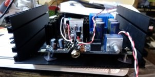
It's an aliexpress opamp, I wanted to try a Chinese amp out of curiosity.
I would definitely fit something we all know 😀 at least for fault finding. The LM833 you mentioned should be good.
Anyone have a good replacement part number for a black knob similar to the silver one, (Parts Express 240-2218)?
40mm like this one on ebay.
Or better yet, spray paint the one you have with metal paint in any color/finish you want that you can find in a can. Holds up really well (an anodized surface is actually a paint priming method), adds the option for more customization. I use a bit of blue tack or similar goo to stuff in the grub screw hole(s)....I've also made knobs with this as a starting point, will have a bit more rebate around it on the Whammy face plate since it's 1.5" and it's a good idea to bore out some weight from the back, and of course you need to drill and tap for a grub screw, etc. But it's super satisfying to touch once it's worked on.
Or better yet, spray paint the one you have with metal paint in any color/finish you want that you can find in a can. Holds up really well (an anodized surface is actually a paint priming method), adds the option for more customization. I use a bit of blue tack or similar goo to stuff in the grub screw hole(s)....I've also made knobs with this as a starting point, will have a bit more rebate around it on the Whammy face plate since it's 1.5" and it's a good idea to bore out some weight from the back, and of course you need to drill and tap for a grub screw, etc. But it's super satisfying to touch once it's worked on.
Last edited:
test
therefore the voltage of R17 connected to the end of R8 is completely stable and the test has been done with the LM 833 🙂
I would definitely fit something we all know 😀 at least for fault finding. The LM833 you mentioned should be good.
therefore the voltage of R17 connected to the end of R8 is completely stable and the test has been done with the LM 833 🙂
Hello guys.
I have been Thinking about building a wammy for both headphone and pré-amp duty.
That would be a recommanded high quality switching jack socket? (If I understood correctly, signal goes to rca output when no jack in, and the signal goes to the Headphone once a jack Is inserted and do stop sound at rca output.
What would be a recommanded high quality volume pot?
Something like dact ? I’d also be really interested to Know if someone succeded in intégrating something like that (VCU | academyaudio) as it also seems like a good option and if si feedback and points or special care/warning... but I may be mistaken.
The whole idear Is to maximise its potential as pre amp duty.
Looking forward to your replies. Best regards.
Noir uses this volume pot: Mouser partnumber 688-RK27112AS-103
and this switching jack: Mouser partnumber 550-20301
For a chrome metal nut instead of black plastic: Mouser P/N 568-NMJ6HCD3-AU
For a "locking" jack (requires different panel cutout! doesn't have switching contacts!) Mouser P/N 568-NJ3FP6C
_
and this switching jack: Mouser partnumber 550-20301
For a chrome metal nut instead of black plastic: Mouser P/N 568-NMJ6HCD3-AU
For a "locking" jack (requires different panel cutout! doesn't have switching contacts!) Mouser P/N 568-NJ3FP6C
_
Last edited:
Dookie182 - Do you want a preamp that can drive headphones or a headphone amp that can be used as preamp?
What use will be 80% of the time?
If you want a preamp and occasionally use headphones, something like Wayne’s BA2018 with the big output devices may be more appropriate.
If you want headphones and occasionally use as preamp, perhaps Whammy will be better.
In either case, both circuits are wonderful sounding and there is no ‘wrong’ answer.
6l6.
Thanks a lot for the fast answer. i guéss the major use will be as a préamp for speaker duty and when Î’d like to as headphone amp. I’ll then look into the other design you refered to.
Still interested anyway on feedbacks relates to volume control. Is there really a set it and Forget it option? Best regards.
I would definitely fit something we all know 😀 at least for fault finding. The LM833 you mentioned should be good.
therefore the voltage of R17 connected to the end of R8 is completely stable and the test has been done with the LM 833 🙂
does anyone have any idea of the cause?
In one of my recent builds I decided I wanted a power indicator LED that stopped glowing the very instant I turned off the power switch. The DC supply rails don't bleed down to zero for many seconds, so I couldn't connect my "pilot light" there; it would remain ON for a long time after the power was switched OFF.
I connected it to the transformer secondary (AC voltage) because that DOES instantly drop to zero when the mains power is switched off. A series diode was installed to prevent the LED from entering reverse breakdown. The diode means I'm applying half wave rectified pulses to the LED, and relying upon persistence of vision to give the perception that this 60 Hertz flickering LED, appears to emit a continuous unchanging beam of light.
The rectifier diode is a 1N3595 because I've got a drawer full of them; they are small and have very low reverse leakage current, so the LED is very well protected. Probably a 1N4148 would have worked well enough. The LED is a wide viewing angle (112 deg) blue diode whose brightness rating is pretty high: 5000 mcd. So I'm running it at about 1 milliamp of RMS current.
_
I'll be doing the same for a power indicator as I'm using the naked regulator version, and would prefer the indicator to be immediate. I'll also be using 1N3595 with some "low current" (2mA @ 2.6V) LEDs, so I'll likely end up using something 1/2W 20-30k resistors to limit current down to only like a milliamp or so.
Couple quick questions:
At what point on the PCB did you connect to the secondaries? Directly to the xformer underneath the PCB?
- Any benefit to adding a small filtering cap for the LED, or not really worth it?
Last edited:
It wasn't a WHAMMY it was a power amp with a big toroidal transformer whose secondary wires attach to the PSU board with screw-cage Euroblox style wire-to-board connectors. So I just jammed the two leadwires of the (LED + rectifier diode + current limiting resistor) assembly, into the same two connector cage holes as the secondary wires, and tightened down the screws. Easy. I never tried a cap because of concerns it might interfere with my instant-off requirement; if you feel like experimenting, do it both ways and pick the one which pleases you most.
Ahh, got it. Thanks. I'll take a look and see what might make the most sense in terms of connecting to V+. Maybe there's already a test point on the PCB after the PSU section (Jim may have alluded to it in the guide)?
I'm also wondering if a switching output jack is beneficial with having preamp out jacks? Is it merely an audiophile desire to have only one active at a time? I suspect that I won't even use the whammy as a preamp, but it's nice to have the option.
I was just planning on connecting a 50R to the same Left, Right, Ground output pads and going from there.
therefore the voltage of R17 connected to the end of R8 is completely stable and the test has been done with the LM 833 🙂
That sounds promising. The voltage you read should be very low indeed, almost zero.
If so then this shows the problem is related to the output stage and not the front end circuitry. It was a quick test but intended to prove just that.
With circuit still connected in this test mode can you also now measure the voltage on the main output (junction of the two 10 ohm resistors). Measure from ground for this.
What voltage do you get?
Is it stable of not?
Also for interest, what voltage do you now see measuring between the 10 ohm resistors. In other words measure from FET to FET across both 10 ohm resistors. Put one meter lead on the FET end of R16 and put the other meter lead on the end of R22 that goes to the other FET.
What voltage do you see?
Attachments
Sp33ls - I’d attach the LED and it’s resistor to one of the filter caps on the bottom of the PCB. Big lugs to attach wires to.
Sp33ls - I’d attach the LED and it’s resistor to one of the filter caps on the bottom of the PCB. Big lugs to attach wires to.
Great, I'll give that a shot! I guess I could attach across the positive and negative leads of same cap right? And if I do that, I wouldn't need that diode then would I
- Home
- Amplifiers
- Pass Labs
- "WHAMMY" Pass DIY headphone amp guide