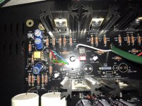
Have you measured DC offset? Your soldering is a bit questionable. You shouldn't have "balls/blobs" of solder. They should be like smooth cones. This happens when you only get heat into the component lead but not on the circuitboard trace. If nobody notices anything more specific, perhaps reflow all the joints.
Thanks for your reply A Jedi,
i'm sorry but you will have to guide me to take these measures. dc offset is voltage between the left and right terminals of the headphone output ? I reread the first page of the thread yesterday to try to find out how to measure but I did not understand everything.
in the meantime I will try to redo my welds.
a few measures
before resolder i would like measuring dc offset and others :
dc offset R 15.6 mv
L do the yoyo
mosfet (if measures are good of course)
R26 R31 0.677
R11 R19 0.49
R29 R32 0.47
R16 R22 0.19
OPAMP (ground R36)
1 : 15.25 v
2 : 0.17 v
3 : 14.91 v
4 : 0.274 v
5 : 14.20 v
6 : 14.30 v
7 : 14.30 v
8 : 30.0 v
if that can give you any ideas
Have you measured DC offset? Your soldering is a bit questionable. You shouldn't have "balls/blobs" of solder. They should be like smooth cones. This happens when you only get heat into the component lead but not on the circuitboard trace. If nobody notices anything more specific, perhaps reflow all the joints.
before resolder i would like measuring dc offset and others :
dc offset R 15.6 mv
L do the yoyo
mosfet (if measures are good of course)
R26 R31 0.677
R11 R19 0.49
R29 R32 0.47
R16 R22 0.19
OPAMP (ground R36)
1 : 15.25 v
2 : 0.17 v
3 : 14.91 v
4 : 0.274 v
5 : 14.20 v
6 : 14.30 v
7 : 14.30 v
8 : 30.0 v
if that can give you any ideas
All voltages should be measured from ground (the zero volt point) and not the from the negative supply which are doing.
DC offset is the DC voltage as measured between ground and the junction of the 10 ohm resistors on the FET's. It should be almost zero volts.
DC offset is the DC voltage as measured between ground and the junction of the 10 ohm resistors on the FET's. It should be almost zero volts.
All voltages should be measured from ground (the zero volt point) and not the from the negative supply which are doing.
DC offset is the DC voltage as measured between ground and the junction of the 10 ohm resistors on the FET's. It should be almost zero volts.
Thanks Mooly for precisions.
so,
FET :
R16 0.12/0.20 it always moves
R22 0.12/0.20 IDEM
R29 0.16
R32 0.17
OPAMP :
for this I don't understand !
earth ground to each
1 : 0.07 8 : 0.20
2 : 0.07 7 : 0.11
3 : 0.05 6 : 0.08
4 : 0.05 5 : 0.06
The parts kit pre-order has been delayed while I gather information from our supplier that the parts described in the text of the sales page are what's in this kit. The photo has been updated with a photo from the new batch, but the description of the parts is still from the last batch.
Would be interested to know what voltage secondaries the transformer has. There has been discussion on the thread of using lower voltage secondaries so that a greater variety of opamps could be used.
Thanks Mooly for precisions.
so,
FET :
R16 0.12/0.20 it always moves
R22 0.12/0.20 IDEM
R29 0.16
R32 0.17
OPAMP :
for this I don't understand !
earth ground to each
1 : 0.07 8 : 0.20
2 : 0.07 7 : 0.11
3 : 0.05 6 : 0.08
4 : 0.05 5 : 0.06
Those last results don't make sense 🙂 Something is wrong with your measurement technique to have no voltage on pins 4 and 8. Make sure the ground point really is ground that you are measuring from.
Look at the circuit diagram. With your negative meter lead on ground (which is any of the points marked with a black triangle) you should see PLUS 15 volts on pin 8 and NEGATIVE 15 on pin 4.
If you are using FET type opamp then pins 3 and 5 should read zero volts.
If you are using a bipolar type opamp then there will be a small (probably negative) voltage on pins 3 and 5 but it should be only a few 10's of millivolts at most. It depends totally on the type of opamp fitted.
new measures
ground pad 12 for all
OPamp :
1 : 0.03 8 : 14.58
2 : 0.09 7 : 0.00 -0.16
3 : 0.09 6 : +0.06 -0.20
4 : 14.96 5 : +0.06 -0.12
dc offset :
R32 0.08
R29 0.08
R22 -0.20 _ +0.22
R16 -0.20 _ +0.22
ground pad 12 for all
OPamp :
1 : 0.03 8 : 14.58
2 : 0.09 7 : 0.00 -0.16
3 : 0.09 6 : +0.06 -0.20
4 : 14.96 5 : +0.06 -0.12
dc offset :
R32 0.08
R29 0.08
R22 -0.20 _ +0.22
R16 -0.20 _ +0.22
Pin 4 should be negative 15v 🙂 It must be correct if the other channel works because it is a dual opamp shared between channels.
So nothing obvious in those results beside the fact there is a small fluctuation.
Here is what I would do and ideally I would use a scope at this point to look what was happening.
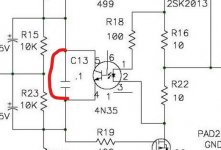
1/ Add a link across C13 to link the bias generator out. Does the fluctuation still occur?
2/ If it was still fluctuating I would for elimination purposes try another opamp. Any common dual type should work to prove the point.
So nothing obvious in those results beside the fact there is a small fluctuation.
Here is what I would do and ideally I would use a scope at this point to look what was happening.
1/ Add a link across C13 to link the bias generator out. Does the fluctuation still occur?
2/ If it was still fluctuating I would for elimination purposes try another opamp. Any common dual type should work to prove the point.
Grounding the Whammy case
Newbie/greenhorn question.
Received the Whammy case yesterday. It's quite nice.
For the past several years my Whammy has been "installed" on a wood board with cardboard on the front and rear to hold the headphone and RCA jacks. It was temporary and it worked.
Because it was temporary and there was no case the gray power lead wasn't connected to anything.
Now there's a case. If I'm reading the instructions properly the gray wire should be connected to the case and from there it should be connected, via a capacitor, to the ground of the RCA inputs.
The case is anodized black. It doesn't conduct, not even through the screws.
So do you sand a bit of finish off the rear panel to make the connection? Or do you have to sand each piece of the case so that there's a connection to every piece of the case?
Thanks for the help!
use star washers in appropriate places, check continuity with DMM
Voilla! , no scratching needed
Voilla! , no scratching needed
Pin 4 should be negative 15v 🙂 It must be correct if the other channel works because it is a dual opamp shared between channels.
So nothing obvious in those results beside the fact there is a small fluctuation.
Here is what I would do and ideally I would use a scope at this point to look what was happening.
1/ Add a link across C13 to link the bias generator out. Does the fluctuation still occur?
2/ If it was still fluctuating I would for elimination purposes try another opamp. Any common dual type should work to prove the point.
1/ you mean bypass C13, for example, with crocodile clip, from below. I connect + to - of C13 ?
Pin 4 should be negative 15v 🙂 It must be correct if the other channel works because it is a dual opamp shared between channels.
So nothing obvious in those results beside the fact there is a small fluctuation.
Here is what I would do and ideally I would use a scope at this point to look what was happening.
1/ Add a link across C13 to link the bias generator out. Does the fluctuation still occur?
2/ If it was still fluctuating I would for elimination purposes try another opamp. Any common dual type should work to prove the point.
If you use croc clips then be sure they are secure and can not slip. Even easier if you are confident is to short the opto pins with metallic tool.
I'm going to try with crocodile clips, right now and opamp's pin 4 is negative, I forgot to specify it.😀
Thanks
results
With bypass to c13 there is less fluctuations.
so, I tried AD823ANZ, first
LM833P
and v4i a chinese's aliexpress
with more or less the same results
With bypass to c13 there is less fluctuations.
so, I tried AD823ANZ, first
LM833P
and v4i a chinese's aliexpress
with more or less the same results
Newbie/greenhorn question.
Received the Whammy case yesterday. It's quite nice.
For the past several years my Whammy has been "installed" on a wood board with cardboard on the front and rear to hold the headphone and RCA jacks. It was temporary and it worked.
Because it was temporary and there was no case the gray power lead wasn't connected to anything.
Now there's a case. If I'm reading the instructions properly the gray wire should be connected to the case and from there it should be connected, via a capacitor, to the ground of the RCA inputs.
The case is anodized black. It doesn't conduct, not even through the screws.
So do you sand a bit of finish off the rear panel to make the connection? Or do you have to sand each piece of the case so that there's a connection to every piece of the case?
Thanks for the help!
The new case has an added hole in the base plate that looks ideally suited for the grounding post. Just follow ZM's advice and use that hole for the post.
And yes, sand or scrape off the anodization if you want to make electrical contact. Generally I will have a number of scraped bare spots on the chassis pieces to get them electrically conductive to each other so they make for a shielding effect.
With bypass to c13 there is less fluctuations.
so, I tried AD823ANZ, first
LM833P
and v4i a chinese's aliexpress
with more or less the same results
So the opamp is 100% ruled out.
It is a strange problem. Apart from the two FET's there isn't much else component wise that could do this, however we need to try and prove all this as non invasively as possible.
This is what I would do next and this will split the circuit into two as far as where the problem lies.
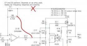
Look at the circuit. If you isolate the end of R8 that goes to the main output and then connect it directly to the 47 ohm as shown here then the voltage on the 47 ohm should then be absolutely steady and at zero volts (if using FET opamp, if bipolar then a very small voltage as I mentioned earlier).
Doing this should prove where the problem lies.
Attachments
So the opamp is 100% ruled out.
It is a strange problem. Apart from the two FET's there isn't much else component wise that could do this, however we need to try and prove all this as non invasively as possible.
This is what I would do next and this will split the circuit into two as far as where the problem lies.
Look at the circuit. If you isolate the end of R8 that goes to the main output and then connect it directly to the 47 ohm as shown here then the voltage on the 47 ohm should then be absolutely steady and at zero volts (if using FET opamp, if bipolar then a very small voltage as I mentioned earlier).
Doing this should prove where the problem lies.
so, how can I do that ?
do I have to unsolder one of the sides of R8 and connect it to R17 and what side (like picture) if it's important ?! 😱
I am really sorry for my total ignorance but this goes way beyond my comprehension, so I prefer that one explains me in detail.on the other hand if I am guided that does not scare me, and in addition it's interesting.
my dear mooly I thank you for your unfailing patience, because with me you did not come across the best 😛
Working from pictures is difficult tbh because I've never seen the real thing, I working of the circuit diagram alone 🙂
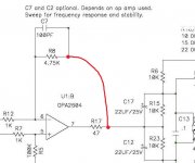
1/ Identify the end of R8 that connects directly to the two 10 ohm resistors. You now unsolder that end to fee it. Just heat the pad and pull the resistor up to isolate that end.
Do not over heat the resistor, be quick. You can also clip a croc clip to the leg to shunt the heat away.
2/ Now identify which end of R17 goes to the two resistors R15 and R23.
3/ Link the end of R17 which you have just identified to the now free end of R8.
Electrically the circuit should look like this. The voltage on R17 (either end) should be absolutely steady.
(What have you got fitted in the IC socket? It looks strange in a picture)
Attachments
- Home
- Amplifiers
- Pass Labs
- "WHAMMY" Pass DIY headphone amp guide