Thank you Rafa,
so I think I just need to switch that led, maybe is in a wrong orientation with led positive arm wrongly inserted on negative pcb pad hole?
It is difficult to comprehend pcb positive position for led because I have a modern led without that “cut off face”, I know led long arm is positive but what about on the pcb?
Is the “cut off face” design on the pcb the positive pole to insert positive long arm led?
Thanks a lot again to you, too.
Best,
DB
The very first page of this thread with the guide has a very useful photo! It shows the LED regulated setup, and has a nice footnote saying D5 is backwards.
Check the schematic. D5 should have it’s positive leg connected to the + of the Cap and the short leg to ground. D6 should have its short leg to the neg leg of its Cap, and the positive leg to ground.
Perhaps simpler, both LEDS need to be physically oriented “the same” in the PCB. So, if you have one that works, match the same physical orientation.
Thank you Rafa,
I really tried to follow along with guide and pictures but sometimes is just difficult when you don't have any idea about what are you doing... I'm very newbie and DIY with electronics so thank you for your patience and yoru support, too.
BTW I changed led with a new one and now both are on.
Measurements now are:
PIN1 -.295
PIN2 14,5
PIN3 14,4
PIN4 -16,45
PIN5 14,3
PIN6 14,5
PIN7 8,1
PIN8 16,32
Everything is ok now or do you guys see something that is still not perfect?
Thanks again to you all!
Mooly thanks!
Just a question: led on D5 stays always off and D6 is always on (with power on of course) is this a normal behaviour or this should be our open circuit to solve?
BTW I will do new measurement later today...
More thanks!
The LEDs are used as low voltage references (like Zener diodes) and should both be lit and passing a few milliamps of current. The LED drops around 2v for a red one and this adds to the 15v of the regulator. It is a text book trick to increase the output of a fixed regulator.
I suspect the incorrectly fitted regulator has either zapped the diode and/or the reg is faulty as well.
If pin 2 has highish voltage present then you could try just shorting the LED out and seeing if the regulator output comes up to 15volts. If it does then the regulator is OK.
If it doesn't come to 15v then both regulator and diode are suspect plus the 330 should be checked.
LOL, always happens that way 🙂
So the LED had gone open circuit by the look of it. In that scenario you should really check the 330 ohm as well on the basis that when the LED failed the resistor may have seen sufficient voltage to damage it. It all depends how much current flowed out of the incorrectly fitted regulator. It is probably OK but should be checked although even if open circuit it would not affect the circuit operation much.
So the LED had gone open circuit by the look of it. In that scenario you should really check the 330 ohm as well on the basis that when the LED failed the resistor may have seen sufficient voltage to damage it. It all depends how much current flowed out of the incorrectly fitted regulator. It is probably OK but should be checked although even if open circuit it would not affect the circuit operation much.
OP AMP suggestion
Hi guys!
Now that finally my Whammy is up and running thanks to Molly and Rafa here on the forum I would like to have some suggestion from you, I’m searching for somemvery intensive users of Whammy amp in order to know what could be the best “neutral” op-amp for a “reference” or “uncolored” sound.
To be clear I would like to hear what is really in the mix and inside the performance itself and not a character of the op-amp.
Wider and more defined soundstage is obviously very appreciated and I do not consider those characteristics like “sound coloration” or eqing.
Maybe I’m searching for a sound engineer recommendation for that op-amp.
At this time I have the LM833N, it seams to sound nice but I’m curious to know if I can improve it accordingly to my needs.
Thanks a lot again to you all!
DannyBarry
Some thoughts on opamps (and without ever having built or listened to one of these).
The OPA2604 was always one of my favourite devices but it was pulled from production ages ago because of problems when run at its maximum supply voltage rating. So any you see are most likely fake parts and could be just dual 741's.
The LM833 is a terrific device... erm... but which version are you using 🙂 as there are two. I think the N version was the old original spec.
Post #72 and post #78
About op-amps use.
Post #2394
The best sounding audio integrated opamps
Quick thought.... the circuit looks as though opamp input bias currents will cause a slight DC offset at the output. FET devices will not do this.
The TL072 has always been a favourite despite many saying it is old and outclassed.
Given that opamps are pretty cheap I'd also suggest you get something that we wouldn't use such as 1458 which is a dual 741... but its a real leveler... going from the worst to top spec devices. See what you think.
If you swap opamps then always check the DC offset at the amplifier output is close to zero before connecting headphones.
Also:
Swapping Op-Amps... you have checked to see it's stable haven't you ?
Regarding the Burson opamps in the store, I assume I would need the Dual opamp x1 for the Whammy - correct?
Last edited:
Regarding the Burson opamps in the store, I assume I would need the Dual opamp x1 for the Whammy - correct?
Yes, if using the pcb from the store. Watch out for the height, location in the case.
@funhouse61
I tested these parts against the € 150, - - 250, - 48 Step SMD potentiometers and couldn't hear any difference.
And relay-based volume controls are available from € 30 with 128 - 256 Steps.[/QUOTE]
Dear Roland968, I'm so sorry, I haven't seen your message in all this time and I apologise again. And I thank you for this information, because I am still looking for a potentiometer that would suit me.
@Jason, JW if you could provide those interested in the chassis any updates on ETA? 🙂
It sounds like the pandemic may have caused some delays with shipping and production?
It sounds like the pandemic may have caused some delays with shipping and production?
Hi everyone ,
I was going to post the exact same question reguarding the ETA on the whammy chassis. I know it’s been in the works for a while. Reading back earlier in the thread I think I remember 6l6 mentioning it was in the works and they weren’t rushing it. So I was curious about a eta on it as well?
@jason also I was curious about the eta on future parts kits for the whammy. Any ideas when or if they will be restocked?
Thanks,
Brandon
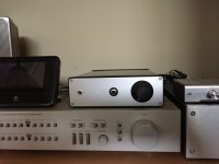
I've had my build for around 2 years now. It's an excellent amp.
Only problem is a hiss when I plug my AD2000X or Denon AHD2000.
One thing I have noticed is that when I switch off the amp, the hiss disappears and the music plays on for a few seconds with no hiss before slowly fading. Any idea what's causing this?
It is not a hum or a buzz, it's a hiss.
I need to mention, C2 and C7 are not used, C26 and C27 are jumpered.
Does that have anything to do with this?
Last edited:
I am going on memory here, but some member here reported that C2 and C7 fixed some hiss in his headphones and Wayne replied “yes, you did the right thing, that is what they are for”. But I have to emphasize I am going on memory, you may want to search the thread for the exact discussion.
I am going on memory here, but some member here reported that C2 and C7 fixed some hiss in his headphones and Wayne replied “yes, you did the right thing, that is what they are for”. But I have to emphasize I am going on memory, you may want to search the thread for the exact discussion.
Here...
https://www.diyaudio.com/forums/pas...-diy-headphone-amp-guide-350.html#post6579257
I have a similar issue when listening through IEMs, I here a very noticeable hiss even around 10 o'clock on the dial, might try installing C2 and C7.
To use WHAMMY as preamp, do I need to put anything between the output pads and RCAs?
I used a 1/4"-to-RCA cord between my WHAMMY and Aleph J and it worked a treat. So direct worked for me. Others may have a different thought. But I thought direct was fabulous.
OP AMP suggestion
Hi guys!
Now that finally my Whammy is up and running thanks to Molly and Rafa here on the forum I would like to have some suggestion from you, I’m searching for somemvery intensive users of Whammy amp in order to know what could be the best “neutral” op-amp for a “reference” or “uncolored” sound.
To be clear I would like to hear what is really in the mix and inside the performance itself and not a character of the op-amp.
Wider and more defined soundstage is obviously very appreciated and I do not consider those characteristics like “sound coloration” or eqing.
Maybe I’m searching for a sound engineer recommendation for that op-amp.
At this time I have the LM833N, it seams to sound nice but I’m curious to know if I can improve it accordingly to my needs.
Thanks a lot again to you all!
DannyBarry
If you want the most neutral op amp in my opinion the Sparkos Labs Dual Op Amp is my top choice
Hi all,
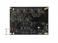
Does anyone have the latest version of the unpopulated WHAMMY PCB from diyaudiostore.com and a pair of vernier calipers sitting in front of them? I'm looking for a specific dimensions for the design of a custom front face.
I'm still waiting for my PCBs to arrive (long postal transit times are one of the downsides of living in New Zealand), but need to get cracking on the custom front faces if I'm to get the completed item to my brother in Singapore in time for his birthday at the end of August.
To that end, I'm looking for a specific dimension (preferably in millimetres please!)from the side of the PCB (as you look at it from the top) to the centre line of through holes on P1 (the attenuator). I've included a photo to explain it better than my words can.
Once I have this dimension I'll be able to dimension the front face cutout for the attenuator.
Thanks in advance 🙂
Attachments
Last edited:
Mr Noisy
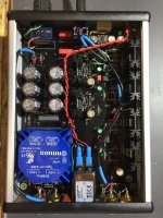
It is not necessary to mount the RK27 Alps pot directly to the PCB. In fact, floating it on leads allows it to be centered vertically on the front panel and (in my opinion) makes drilling and mounting it easier.
It is not necessary to mount the RK27 Alps pot directly to the PCB. In fact, floating it on leads allows it to be centered vertically on the front panel and (in my opinion) makes drilling and mounting it easier.
Attachments
- Home
- Amplifiers
- Pass Labs
- "WHAMMY" Pass DIY headphone amp guide