Remind me again, what it the impedance of your other headphone? I am not very versed in electronics, but I have to ask if you can't just place a resistor on the cable of the headphone with the lower impedance and match the Beyers? it doesn't really make any difference if you change the gain with a resistor internally or externally does it?
To my understanding, and correct me if I'm wrong, inserting a resistor on the output of the ap\mp makes that resistor value the output impedance that the load sees- and definitely has an effect on the sound you hear.
In any event, the Etymotic IEMs are 45Ω, the Beyers are 250Ω.
Last edited:
Yeah, I know... Point taken and no offense intended to Wayne... I'm pretty sure that what he has forgotten about audio design exceeds what I will ever know… You're telling me audibly quiet with IEMs...?It’s interesting how you are finding the designer “hard to believe”.
Last edited:
You could also build (or have made) an output 'power soak' adapter (simple 2 resistor attenuator/channel in a plug & socket adapter) that's added with the more sensitive units when plugged in - an old idea - this'll save you playing around with the feedback 'stuff' and easily changed.
You could also have 2 output sockets on the case, one that includes these resistors to reduce the volume.
I must say that the 'Whammy' produces an excellent sound and you might find that you just like it a 'bit louder' anyway!
I don't use any of the IEMs as they just don't 'fit well' but I do use the same Beyer 880/250R, Senn 650s, AKGk701 & 2s, and my modded HE500s - this amp just seems to work well with all of them and worth persevering.
diyAudio Store product "Noir" has a gain of 2 (+6.0dB) and some builders complain that their line-level source's output is so low, that 2x that output, doesn't play loud enough for their headphones. The amp itself can drive WAY more voltage and WAY more current, but unfortunately (2 x a-small-input) is still pretty small.
FYI
FYI
just make it with gain of 2 and it will cover even you wildest can combos
Probably so, but when the designer, who knows the design better than anyone, is discouraging me from playing with the gain... I'm inclined to listen to him
Well, yeah, but then I've got two construction projects instead of one...You could also build (or have made) an output 'power soak' adapter (simple 2 resistor attenuator/channel in a plug & socket adapter) that's added with the more sensitive units when plugged in - an old idea - this'll save you playing around with the feedback 'stuff' and easily changed.
This would also raise the output impedance significantly.You could also have 2 output sockets on the case, one that includes these resistors to reduce the volume.
I'm sure the Whammy sounds great. My present amp will play at hearing-threatening levels so I'm good.I must say that the 'Whammy' produces an excellent sound and you might find that you just like it a 'bit louder' anyway!
Those examples do seem kind of like the 'target audience' for the design. I 'm sure it would be great with the Beyers. I'm not so sure about the IEMs, At the 'hi' setting (3.4x) I have very little volume control range before it gets loud. This amp adds another 3dB or so. So we'll see.I don't use any of the IEMs as they just don't 'fit well' but I do use the same Beyer 880/250R, Senn 650s, AKGk701 & 2s, and my modded HE500s - this amp just seems to work well with all of them and worth persevering.
Last edited:
Probably so, but when the designer, who knows the design better than anyone, is discouraging me from playing with the gain... I'm inclined to listen to him
I believe point of Wayne's post was - build and see
and, you can change it later
First post on diyAudio.
Thank you to Wayne, 6L6 and everyone who has contributed here who've made building this possible.
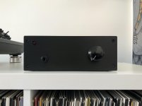
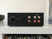
The Whammy is the first diyAudio project that I've completed, I'm definitely hooked! I built two, one with a 15v supply for my friend who wanted to run the Muses01 opamp risk free, and this one for my self with the 17v supply. Please could someone with more experience provide some knowledge in a couple of areas?
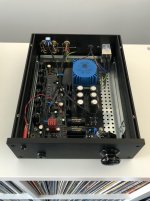
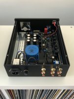
1: After building my Whammy I have since read a couple of posts that suggest that the 25va, 2x15v transformer that I selected may not have been the correct choice for the LED supply configuration. The part looks pretty difficult to desolder with the equipment I have on hand, could anyone offer some guidance on this? I would really like my amp to perform at it's best, Is there any point in swapping the transformer out?
2: If I connect headphones to the switched jack with the preamp outs connected to my amp i get some noise coming through the speakers. I have tested this on a couple of friends systems and it is has been inaudible, however on my 101dB speakers you can definitely hear it. Is there anything obvious from the photos that I could do to fix this?
Thanks!
Thank you to Wayne, 6L6 and everyone who has contributed here who've made building this possible.
The Whammy is the first diyAudio project that I've completed, I'm definitely hooked! I built two, one with a 15v supply for my friend who wanted to run the Muses01 opamp risk free, and this one for my self with the 17v supply. Please could someone with more experience provide some knowledge in a couple of areas?
1: After building my Whammy I have since read a couple of posts that suggest that the 25va, 2x15v transformer that I selected may not have been the correct choice for the LED supply configuration. The part looks pretty difficult to desolder with the equipment I have on hand, could anyone offer some guidance on this? I would really like my amp to perform at it's best, Is there any point in swapping the transformer out?
2: If I connect headphones to the switched jack with the preamp outs connected to my amp i get some noise coming through the speakers. I have tested this on a couple of friends systems and it is has been inaudible, however on my 101dB speakers you can definitely hear it. Is there anything obvious from the photos that I could do to fix this?
Thanks!
Attachments

Wow read this entire topic! Some posts several times. Took the better part of 3 nights. I may have missed this but I would like to run < 15 volt rails but want to keep D5 and C10. Is this as simple as running 7812/7912 regulators and maybe swapping to a 2.6 volt green LED for roughly 14.6 volts. I may want to go with a 12 or 15 volt output transformer. If I do not use the LED/capacitor, I should be able to run R9 (182 ohm) and R10 (750 ohm) for a rail voltage of roughly 14.9 volts. I have a bunch of high end OP Amps from other projects I would like to try.
Thanks to everyone for all of the input. Wayne and Jim you must have the patience of a female elephant. They are pregnant for 22 months and their calves never leave the mothers side.
Thanks to everyone for all of the input. Wayne and Jim you must have the patience of a female elephant. They are pregnant for 22 months and their calves never leave the mothers side.
I believe point of Wayne's post was - build and see
and, you can change it later
A little bit of a PITA to change after he fact tho... Although I could socket the gain setting R's as was done in my O2 to make them easy to change later if desired.... hmmm....
I still have the feeling that something short of 4.7 is going to turn out to be the best approach and then change if necessary (based on the gain settings in my present amp), but I'll try it... Looks like a fun 'build' at the very least.
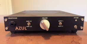
For what it's worth, one of the headphone amplifiers I exhibited at Burning Amp 2019, had two gain settings: +16.3dB and +8.0dB ; or, if you prefer, 6.5X and 2.5X. With these choices, the HPA paired quite well with a large number of different sources and different source signal amplitudes.
Gain switching in this particular unit was performed with relays, whose coils are activated by a front panel toggle. Of course other implementations would work quite well, too.
It was a great pleasure to hand over the headphones to Wayne C. for a demo and listening evaluation of Azul, at the end of the B.A.F. He was very kind.
_
Attachments
Probably so, but when the designer, who knows the design better than anyone, is discouraging me from playing with the gain... I'm inclined to listen to him
I think Wayne was just suggesting you build it as is and then see where you are. Messing with the gain is pretty simple, if you should need to do it. I've done it just recently myself. The stock values give me very little room to play with the volume control, so I increased R1 and R12 a couple times. (I think I have 4.75K in there now.)
There's no reason you can't add a switch, say, that adds an additional resistor in line with R1 and R12. Alternatively, solder some kind of socket where the resistors are supposed to go and swap them manually when you need to do so.
My suggestion, like Wayne's, would be to build it stock and then play with it if you need to do so. It's really not difficult to do. The resistors are readily accessible. The trick, for me, is to trim the new resistors to the right size ahead of time and then just melt the solder that's still there and insert the pin. Easy peasy. Don't even have to take the board out of the case.
Last edited:
Another way to skin the cat is to use a multi turn pot for the volume control (or encoder), have a look at this
Muses Volume
OneDrive
Muses Volume
OneDrive
I think Wayne was just suggesting you build it as is and then see where you are. Messing with the gain is pretty simple, if you should need to do it. I've done it just recently myself. The stock values give me very little room to play with the volume control, so I increased R1 and R12 a couple times. (I think I have 4.75K in there now.)
There's no reason you can't add a switch, say, that adds an additional resistor in line with R1 and R12. Alternatively, solder some kind of socket where the resistors are supposed to go and swap them manually when you need to do so.
My suggestion, like Wayne's, would be to build it stock and then play with it if you need to do so. It's really not difficult to do. The resistors are readily accessible. The trick, for me, is to trim the new resistors to the right size ahead of time and then just melt the solder that's still there and insert the pin. Easy peasy. Don't even have to take the board out of the case.
A socketed setup would seem easier than soldering with every change; I go back and forth quite a bit, and in addition to being a chore, seems like the trace would eventually lift. A switch would be the easiest long-term but simplest would be finding a gain setting that works for both if I can. Thanks all.
WhatFirst:
Keep in mind when calculating desired opamp power supply voltages that the opamp rails will see less voltage than the main supply rails due to the 47 ohm resistors in series feeding power to the opamp. When using the red LED reference and 15V regulators (main rails just over +/-17V), I measured around +/-15.5V at the opamp itself. Shorting R9 and R13 to provide the standard +/-15 main rails would put the opamp voltages at well under +/-15V.
Keep in mind when calculating desired opamp power supply voltages that the opamp rails will see less voltage than the main supply rails due to the 47 ohm resistors in series feeding power to the opamp. When using the red LED reference and 15V regulators (main rails just over +/-17V), I measured around +/-15.5V at the opamp itself. Shorting R9 and R13 to provide the standard +/-15 main rails would put the opamp voltages at well under +/-15V.
All of this reminds me that the Aleph P, of which I owned two, has adjustable gain via two rotary switches on the front panel. On this schematic here, it appears to be the pot right in the middle. Presumably one could wire up something similar for the Whammy with, say, a 10K pot in series with the 1k resistor. I may even try that...
avdesignguru
Thanks for the great feedback. I was planning to build an as designed unit first in a larger case. I have a couple of 2U Galaxy chassis (230 x 280) collecting dust. Then I could add a couple of inputs and a line out after the amplifier is up and running. This unit would be used both for my headphones and a set of high-end powered speakers. The question I was asking was for a second headphone only amp but in a much smaller case and trying to minimize heat. I was curious if anyone had tried smaller 12v regualtors but your measurements may get me in the ballpark for most of my current opamps.
Thanks for the great feedback. I was planning to build an as designed unit first in a larger case. I have a couple of 2U Galaxy chassis (230 x 280) collecting dust. Then I could add a couple of inputs and a line out after the amplifier is up and running. This unit would be used both for my headphones and a set of high-end powered speakers. The question I was asking was for a second headphone only amp but in a much smaller case and trying to minimize heat. I was curious if anyone had tried smaller 12v regualtors but your measurements may get me in the ballpark for most of my current opamps.
- Home
- Amplifiers
- Pass Labs
- "WHAMMY" Pass DIY headphone amp guide