Just bought a stack to be populated later.
When I built my first Whammy I remember freaking out a little when I measured the input voltage going to the voltage regulators as showing up as about 36vdc. I was building the DIYStore kit so I figured this had been tested by a number of folks and so I didn't need to worry about it. I installed the kit caps that are rated at 35vdc, as is printed on the circuit board.
Recently during building my second Whammy, I noticed this again and decided to do some more investigation. @Gaz2613 created a nice board that is just the supply side of the Whammy including the regulators, so I decided to build that and do some testing. After putting this together, I double-checked last night and I am measuring 37VDC on the last set of caps on the supply. I am wondering if the 35VDC-rated caps are sufficient, including longevity of the caps. I’ve always been taught to use ~2x the rating
of any cap, which this seems to be cutting it a bit close. I am using Nichicon KA(M) 3300uf @ 50V caps but is that over kill?
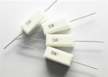
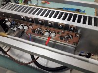
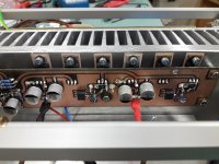
Suppose a crazy person were to look at the photographs attached to post #2 of this thread. Suppose a crazy person focused her/his attention upon the sixth and seventh images attached to post #2: the ones with the yellow-insulated and blue-insulated jumper wires. This is a legitimately crazy person, someone who has been clinically diagnosed as "farking insane".
Suppose this crazy person decided to remove those jumper wires and replace them with cement-packaged 5 Watt resistors. Suppose this crazy person hired an equally crazy but experienced designer, Doctor Emilio Lizardo, to calculate the desired values of those 5 Watt resistors.
Now, I ask the completely hypothetical question: what would be the effect of replacing the jumpers by 5 Watt resistors? And how crazy would that be?
edit- here's an image
_
Attachments
Last edited:
Thomas -
Where exactly were you measuring? The kit has a 22VAC transformer, 22VAC x 1.414 for rectification gives 31.1v dc before the diodes, then you’ll lose another 0.7v across two diodes, bringing it down to 29.7, before the filter resistors drop a little more.
36V seems more than a little high, even unloaded. Were you perhaps measuring across the entire supply from V- to V+. Instead of from GND to V+ and GND to V-?
Just trying to understand the mystery...
Suppose a crazy person were to look at the photographs attached to post #2 of this thread. Suppose a crazy person focused her/his attention upon the sixth and seventh images attached to post #2: the ones with the yellow-insulated and blue-insulated jumper wires. This is a legitimately crazy person, someone who has been clinically diagnosed as "farking insane".
Suppose this crazy person decided to remove those jumper wires and replace them with cement-packaged 5 Watt resistors. Suppose this crazy person hired an equally crazy but experienced designer, Doctor Emilio Lizardo, to calculate the desired values of those 5 Watt resistors.
Now, I ask the completely hypothetical question: what would be the effect of replacing the jumpers by 5 Watt resistors? And how crazy would that be?
edit- here's an image
_
Assume there is an equally crazy, but far less knowledgeable, person that loves puzzles and just happens to be building a very simple knowledge base re: circuits in the early morning hours over a cup of coffee. Further assume that this person had just recently read the thread linked below for the umpteenth time while also attempting to learn basic oscilloscope measurement techniques and assembling a lexicon of curse words. It could also be assumed that this person doesn't know their rump from their elbow.
Evidence of this person's craziness is that they are willing to toss a WAG into a public internet forum that said resistor(s) could affect the ringing from the transformer and share their reasoning. Those resistor(s) would be placed across the mains AC and the transformer primaries. This could be similar to RS1 in the UPS v3.0 which is placed after the AC step down from the transformer, across the secondaries, but prior to rectification. Said nutter seems to recall that RS1 acts as a "snubbing" resistor. Assuming that AC "ringing" could propagate across the primary / secondary gap, snubbing could also be effective on the "primary side". One could put a hand on the bell in either place. Then said person, having never been bothered much by internet mockery, would stand proudly by that WAG and wait for flying tomatoes.
This concept offered by the crazy Buckeroo may be quite sound when compared to the idea of removing the transformer from a perfectly functioning WHAMMY to test such a theory.
Simple, no-math transformer snubber using Quasimodo test-jig
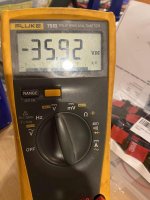
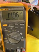
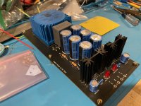
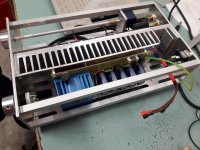
It took me a bit because I triple-checked how things are setup. The only differences I had from the stock Whammy PSU was that I had originally used a 440V-reated X2-cap across the secondaries and I used 1N007 diodes as that is what I had around. I replaced the X2 cap with the stock one with no changes. I can't imagine higher-current rated diodes are the problem, so I left those in. I am also using 3300uF @ 50V Nichicon caps instead of the stock 35v-rated ones.
As you can see from the pictures, post-the SparkOS +/-15v regulators, I am getting +15v and -15v as expected BUT the other measurement was taken at the same time connecting the other DVM to the legs of the last cap (note my probes were connected backwards, hence the inverted voltage but both show the same voltage at the caps - about 35V.
As you can see from the pictures, post-the SparkOS +/-15v regulators, I am getting +15v and -15v as expected BUT the other measurement was taken at the same time connecting the other DVM to the legs of the last cap (note my probes were connected backwards, hence the inverted voltage but both show the same voltage at the caps - about 35V.
Attachments
Looking at the datasheet for your transformer (look for 70065K on page 22):
https://talema.com/wp-content/uploads/datasheets/Transformer-Catalog.pdf
it states the unloaded secondary voltage is 26.2VAC. This will get you a few
more volts DC. (And it doesn't look like you have much of a load on the PS).
Also, your raw AC voltage might not be exactly 115VAC and that will affect things too.
That is the key that I missed. The non-loaded secondary is 26.2, so using 6L6's math above we get 26.2 * 1.41 = 36.942v which is right around what I am seeing. I am getting 35.9v at the caps which is due to the diode and resistor drops along the way. Thanks for straightening this out for me folks. 🙂
So my question is: is this too high for 35V-rated caps? I know that this is unloaded, and once you build the rest of the circuit it gets loaded down to voltages that are within the tolerance, but if you build these things incrementally as I tend to do, you might get an unexpected surprise.
--Tom
So my question is: is this too high for 35V-rated caps? I know that this is unloaded, and once you build the rest of the circuit it gets loaded down to voltages that are within the tolerance, but if you build these things incrementally as I tend to do, you might get an unexpected surprise.
--Tom
So my question is: is this too high for 35V-rated caps?
The simple answer is they will be fine for a short time. However, commercial amp designers will de-rate components, especially electrolytics for a reason.
You need to figure out what the transformer loaded voltage will be in an idle state to really answer this question.
More info for you: Running caps near voltage limit
Hi Guys,
We have a few free samples available for the next month. Please pm me if you would like to test our opamps.
Supreme Sound Opamp V5i – Burson Audio
Supreme Sound Opamp V6 – Burson Audio
Thank you.
Happy listening!
We have a few free samples available for the next month. Please pm me if you would like to test our opamps.
Supreme Sound Opamp V5i – Burson Audio
Supreme Sound Opamp V6 – Burson Audio
Thank you.
Happy listening!
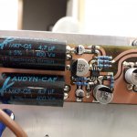
I strongly recommend the V6 vivid for the Whammy. It is amazing to me. I did not like the v6 classic on the other end. A matter of taste maybe.
Yes, its all about our own hearing taste but also, the type of power supply caps and local bypass caps on the IC's power pins effect the V6 performance quite a bit too - there's quite a bit of flexibility to these ICs.
I borrowed from my friend and listened with vivid and classic V6;
I went for vivid. It is invincible.
My other friend suggests Sparkos Lab’s SS3602 discrete opamp.
Does anyone have a good review on SS3602?
I went for vivid. It is invincible.
My other friend suggests Sparkos Lab’s SS3602 discrete opamp.
Does anyone have a good review on SS3602?
I found them to be a bit too bright for me in comparison to the Burson V6 ICs, but they did okay with my old Senn 650's but a rather "brittle" sound with the AKG k701 or the HE-500 - I'm using the Ayre QB-9 dac (or the Codex) and both of these have a neutral sound.
It's quite hard to use these opinions to evaluate what these component choices will mean to your listening but perhaps some comparisons might give you a starting point - also, a lot depends on the type of music you prefer, etc, etc
It's quite hard to use these opinions to evaluate what these component choices will mean to your listening but perhaps some comparisons might give you a starting point - also, a lot depends on the type of music you prefer, etc, etc
Yeah. I agree with this.
Denon AH-D7000 sound very different to AKG K700.
I could certainly imagine the Vivid being too much of a good thing with the K700.
Denon AH-D7000 sound very different to AKG K700.
I could certainly imagine the Vivid being too much of a good thing with the K700.
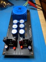
New try on mostly SMD Whammy.
First testrun finished successfully.
No burning components till now 🙂
Final wiring required to test the sound.
No OP amp rolling possible I have settled on AR823.
Hopefully this was not a mistake.
Testet in my old Whammy with OPA 2604 but wasn`t much impressed.
Some tested the AR823 in the whammy results sound not so bad.
Attachments

well, that's so Industrial Fugly!
reminds me of best made Studer modules
🙂
edit - do not forget nice flat washers and split-washers , on these M3 holding mosfets ( if you already didn't put black cone washers, can'see detail properly)
I know your construction will never go hot, so plastic bushings will last, but that's proper practice
Last edited:
I borrowed from my friend and listened with vivid and classic V6;
I went for vivid. It is invincible.
My other friend suggests Sparkos Lab’s SS3602 discrete opamp.
Does anyone have a good review on SS3602?
Its a matter of taste in my experience. I've personally tried 14 of them and settled on either of the discretes, and have Papa's discrete on my list to hand-build one of these days too. I settled on the Sparkos Lab's dual discrete opamp for my first Whammy, but I'll likely use one of the Bursons in the one I am building now. You will find that both of these discretes are far above any of the opamps rolled in this thread and both sound awesome.
No OP amp rolling possible I have settled on AR823.
Maybe do you mean the AD823 which is a JFET input, dual opamp from Analog Devices?
Google finds no opamps called AR823 ...
- Home
- Amplifiers
- Pass Labs
- "WHAMMY" Pass DIY headphone amp guide