Whammy volume?
Good morning all..
First time caller here.. Want to say thank you to all of you who have contributed to this thread! 6L6, Wayne, and my friend pfarrell for a LOT of help and convincing this NOOB to attempt to build my first audio DIY project!
The build went pretty smoothly, although I did have to remove two resistors that I accidentally included that were not supposed to be included for "LED reference" version. No big, other than that, it went really smootly, albeit slowly (I went really slow..) After building the PSU supply side, I was able to verify voltages were correct +/-. I think it was 16v both positive and neg.. (ish)
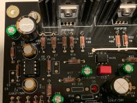
Proceeded on and finished up the AMP side yesterday, case still needs to be finished up and drilled, but I was able to power it up, and to my surprise, I actually had AUDIO in my headphones! (Step 1. Hear stuff)
I think that I have an issue somewhere though because at max volume on the POT, it sounds 'fine'.. but def not loud.. pfarrell says it should be louder than comfortable at max..
Setup and things I've tried: Whammy built mostly per specs in the build guide. Used some shorter caps (at pfarrell suggestion) @opamp. Using 833N for opamp initially. (I have a few others I could try?)
Connections all yielding volumes less than desired:
iMac w/ Tidal, USB --> Modi Mulitbit --> Whammy
iPhone --> Modi --> Whammy.
iMac w/ Tidal --> 3.5mm/RCA --> Whammy
iPhone --> 3.5mm/RCA --> Whammy
This morning I grabbed a 3.5mm to RCA cable and tried cutting out the Modi just to rule it out as a possiblity without success.
Hoping someone has some guidance, or sees something glaring that I've done wrong! As I've told pfarrell, please assume that I know nothing.. That's largely true! Thanks for any and all assitance!
Cheers all!
Good morning all..
First time caller here.. Want to say thank you to all of you who have contributed to this thread! 6L6, Wayne, and my friend pfarrell for a LOT of help and convincing this NOOB to attempt to build my first audio DIY project!
The build went pretty smoothly, although I did have to remove two resistors that I accidentally included that were not supposed to be included for "LED reference" version. No big, other than that, it went really smootly, albeit slowly (I went really slow..) After building the PSU supply side, I was able to verify voltages were correct +/-. I think it was 16v both positive and neg.. (ish)
Proceeded on and finished up the AMP side yesterday, case still needs to be finished up and drilled, but I was able to power it up, and to my surprise, I actually had AUDIO in my headphones! (Step 1. Hear stuff)
I think that I have an issue somewhere though because at max volume on the POT, it sounds 'fine'.. but def not loud.. pfarrell says it should be louder than comfortable at max..
Setup and things I've tried: Whammy built mostly per specs in the build guide. Used some shorter caps (at pfarrell suggestion) @opamp. Using 833N for opamp initially. (I have a few others I could try?)
Connections all yielding volumes less than desired:
iMac w/ Tidal, USB --> Modi Mulitbit --> Whammy
iPhone --> Modi --> Whammy.
iMac w/ Tidal --> 3.5mm/RCA --> Whammy
iPhone --> 3.5mm/RCA --> Whammy
This morning I grabbed a 3.5mm to RCA cable and tried cutting out the Modi just to rule it out as a possiblity without success.
Hoping someone has some guidance, or sees something glaring that I've done wrong! As I've told pfarrell, please assume that I know nothing.. That's largely true! Thanks for any and all assitance!
Cheers all!
Attachments
-
 IMG_7043.jpg431 KB · Views: 383
 -
 IMG_7039.jpg671.5 KB · Views: 184
 -
 IMG_7041.jpg629.2 KB · Views: 194
 -
 IMG_7042.jpg401.8 KB · Views: 200
 -
 IMG_7037.jpg540.7 KB · Views: 190
 -
 IMG_7040.jpg605 KB · Views: 193
 -
 IMG_7038.jpg730.3 KB · Views: 340
 -
 IMG_7044.jpg758.2 KB · Views: 365
 -
 IMG_7045.jpg546.1 KB · Views: 377
 -
 IMG_7036.jpg655.2 KB · Views: 383
I'm wanting to build one of these with some Takman caps I found at a yard sale. These seem to come in different sorts of values from other resistors. (I gather there are two kinds of series?) The only at all significant difference is R11,19,26,31: The closest Takman is 510R. That's about a 2% difference, so shouldn't matter much at all. But I'm just curious: What kind of difference does changing that resistor make? I'm a novice with this stuff, but it seems to control the current presented to the MOSFETs, right? Increasing it would therefore decrease the current, yes? With what effect?
Good morning all..
Hoping someone has some guidance, or sees something glaring that I've done wrong! As I've told pfarrell, please assume that I know nothing.. That's largely true! Thanks for any and all assitance!
Cheers all!
What value volume pot are you using?
What headphones are you using?
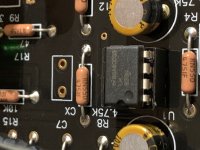
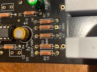
1) Check values of R39 and R40 that they are 2.2k and not something higher eg 22k
2) Check R2 and R7 is 1k
3) Check R3 and R5 are 100k
4) Check R4 and R8 are 4.75k
5) Check R1 and R12 is 1k
That is a start.
It could possibly just be your headphones.
I will have a look at the photos.
Ok this could be it.
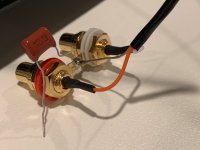
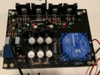
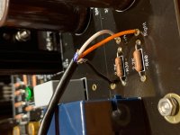
I don’t see any circuit connections to the 0V star on the RCA ground pins.
All I see is a shield wire connection but no other circuit connections.
Maybe there is a connection but it’s not clearly seen at the pcb
I don’t see any circuit connections to the 0V star on the RCA ground pins.
All I see is a shield wire connection but no other circuit connections.
Maybe there is a connection but it’s not clearly seen at the pcb
Last edited:
I could be wrong, but I think the cable shield is being used for ground, and that it is attached to the ground point near the input pads. (Amusingly, this is also hard to see in 6L6's build guide.) But I could be wrong.
DO THIS FIRST
One more thing.
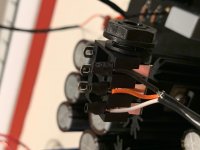
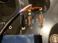
On the rca jacks, I see that one of the ground pins is sitting between the WHITE insulating washers and possibly not making good electrical contact.
Move the position of this so it’s in direct contact with the tightening nut and make the nut tight against it.
Fix this first and report back immediately.
One more thing.
On the rca jacks, I see that one of the ground pins is sitting between the WHITE insulating washers and possibly not making good electrical contact.
Move the position of this so it’s in direct contact with the tightening nut and make the nut tight against it.
Fix this first and report back immediately.
Last edited:
Please read through the article referred to above on diyaudio; it does a fantastic job explaining how the 3 different paths to ground work (with a bunch of other relevant information about ground loops etc...).
Thanks for pointing me to that. It really is great!
I keep thinking that something a bit more like a wiki would be great here, so links to things like that could be collected somewhere and made more easily accessible. I know there are the pinned things, but that is a blunt instrument.
DO THIS FIRST
One more thing.
On the rca jacks, I see that one of the ground pins is sitting between the WHITE insulating washers and possibly not making good electrical contact.
Move the position of this so it’s in direct contact with the tightening nut and make the nut tight against it.
Fix this first and report back immediately.
Probably dumb and only slightly related question, but safety first....
I've built cases for my Whammy's out of wood. Now I know that this won't provide shielding for the circuitry. But is there anything else I should consider, e.g., safety-wise, especially? I can obviously run wires from anything that might get electrified to safety ground, but what might that be? I have a metal power switch on the front panel on one build, and I'm thinking I should probably run a wire from what would normally connect to the chassis to safety ground (in case the AC line somehow got connected to the toggle switch itself). Yes?
What about the knob on the pot?
You can get shielding by internally lining your wooden case with aluminium foil or aluminium tape etc, then connecting to the mains earth wire.
I have a metal power switch on the front panel on one build
If that switch is directly connected to mains voltages 120/240V that is very dangerous.
A switch like that I would use as a low bias energy saving switch, or combine with a relay that operates at lower voltages to turn the power on.
And yes the switch housing should be connected to mains earth.
You can get shielding by internally lining your wooden case with aluminium foil or aluminium tape etc, then connecting to the mains earth wire.
Thanks. I've thought about doing that. It's easy to get some thin metal parts at Lowes....
I assume the thickness matters? How much?
Thickness doesn’t matter too much, just making sure you have a low impedance connection to earth.
Get what ever thickness you feel is easiest to use.
You could even internally line using aluminium tape.
Get what ever thickness you feel is easiest to use.
You could even internally line using aluminium tape.
Last edited:
Thanks again! I thought about doing that but was not sure if it would be worth it. I'll try it and report back later.
I don't think I posted photos of the build in this thread. Photos here. The body is jatoba, but the top is simple luan. I've since learned how to apply veneer, so Mk II has a redwood body and cherry veneered top. Pix to come.
I don't think I posted photos of the build in this thread. Photos here. The body is jatoba, but the top is simple luan. I've since learned how to apply veneer, so Mk II has a redwood body and cherry veneered top. Pix to come.
You can do a measurement how it is now, then get some scrap aluminium and connect to mains earth and put it underneath the chassis then remeasure for noise, then put it on top and remeasure for noise.
If you don’t see any improvements then you don’t need to worry about it.
Although it will also prevent noise being radiated out of the headphone amp.
It’s not always necessary.
If you don’t see any improvements then you don’t need to worry about it.
Although it will also prevent noise being radiated out of the headphone amp.
It’s not always necessary.
What value volume pot are you using?
What headphones are you using?
1) Check values of R39 and R40 that they are 2.2k and not something higher eg 22k
2) Check R2 and R7 is 1k
3) Check R3 and R5 are 100k
4) Check R4 and R8 are 4.75k
5) Check R1 and R12 is 1k
That is a start.
It could possibly just be your headphones.
I will have a look at the photos.
picoDumbs,
Thank you for looking into this with me.. POT is an Alps 50k, headphones are Fostex TH-X00's.. (Plenty of volume from them when being driven by another source)..
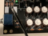
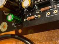
I reconfigured the RCA jacks this morning and moved the ground pins so that they are in direct contact with the rear nut, unfortunately without change in the volume. Also, I checked the resistors mentioned above, and took pictures.. I think that they are all correct, but would you mind verifying that I'm reading them correctly? Pics attatched..
Also, the ground wire from RCA is connected to the PCB.. Using shielded mic cable, so I used the 3rd wire in that bundle that was not coated for the ground.. I"m assuming that's correct? Not the metal sheathing..
Thanks so much!
John
Attachments

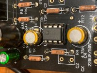
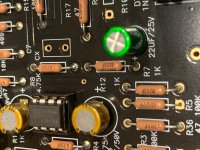
With R5 and R3 I would expect to see it labelled as 1003F not 1000F but that's assuming the same naming convention as 1002F for 10K.
I will try and find the naming convention for 100K
I will try and find the naming convention for 100K
I think 1000F could actually be 100 Ohms not 100 K
Pretty sure 100K should be labelled 1003F
1 Meg is definitely 1004F.
10 K is definitely 1002F.
Pretty sure 100K should be labelled 1003F
1 Meg is definitely 1004F.
10 K is definitely 1002F.
Last edited:
picoDumbs,
Thank you for looking into this with me..
John
This is your problem.
Replace R3 and R5 with 100K resistors
After you fix it make sure to turn the pot back to minimum.
Last edited:
- Home
- Amplifiers
- Pass Labs
- "WHAMMY" Pass DIY headphone amp guide