@banderson546
What attenuator did you use? Value?
Nothing Fancy - A standard Dual Audio Taper 10K pot 🙂
Well, I'm starting to get there.... I have dual VRDNs in one box all done and working. I have dual umbilicals done and waiting to finish the second box which will have the 18, volume and switch. Mine will be a 3 in and 1 out, but with an option to drop in another and make in and two out one VRDN for each board.. Might be cool to play with it and drive 2 Mx2 for 4 speakers lol.
Anyway, pics up as soon as I test the finished 18 in the box... I'm stoked about this amp... this one will probably stay in the lab and drive my dual mono MX2 or the J2 or the... 🙂=
Thanks for all the help, and all that I will ask in the future, love this forum.
JT
Anyway, pics up as soon as I test the finished 18 in the box... I'm stoked about this amp... this one will probably stay in the lab and drive my dual mono MX2 or the J2 or the... 🙂=
Thanks for all the help, and all that I will ask in the future, love this forum.
JT
...it gets louder. 😀
But I'm not actually trying to be a wiseguy with that comment. The preamp sounds the same at all volume levels, the thing of note is that BA2018 sounds very good at low levels... and that's actually quite difficult to do.
Plenty of systems sound good turned up. Not all sound good when playing softly...
And that mostly depends of the speakers used...
...it gets louder. 😀
But I'm not actually trying to be a wiseguy with that comment. The preamp sounds the same at all volume levels, the thing of note is that BA2018 sounds very good at low levels... and that's actually quite difficult to do.
Plenty of systems sound good turned up. Not all sound good when playing softly...
Very good. Was hoping for the smoker feedback as to what he thought of the sound at higher volumes. Sol good
to Monk 55
Hello Monk55,
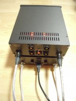
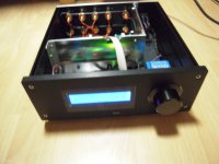
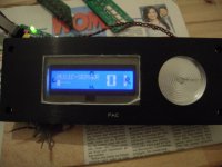
I have built my Waynes Line Stage in 3 cases:
-one case for the preamp
-one case for the PSU
-one case to control inputs and volume.
My WLS is a dual - mono - construstion (o.K., both channels in one case -
some call this monoaural....).
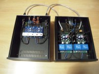
I have spent a lot of efforts on a silent PSU. I also selcted / matched all Toshiba -SMD-JFets, matched the OnSemi/Fairchild - BJTs and used
matched Toshiba TTA004/TTC004 output-BJTs (because i use my WLS also
as a headphoneamp). I also matched each resistor from left to right channel....
How does it sound?
It sounds extremely detailed and clear in the mids and highs - no harshness.
The bass is solid and controlled. The soundstage - depth and room information
is at a very high level. This is independent of how I set the volume pot.
This is an excellent preamp - I would call it -state of the art-.
It drives all my poweramps with ease (BA-3, BA-1-Monoblocks, F5-T-Monoblocks, M-2X and also my 50W-SE-Schade-amp-Monoblocks).
And it is extremely silent - or lets say 'unnoisy'.
This preamp is at the moment in the top 3 of my DIY-preamps (together with the B1-Korg-NUTUBE-pre and the ACP+ -pre.
And a last sentence: It always sounds as a chain - your whole system!
From the source to the loudspeaker - and all inbetween
My opinion?! 🙄
Greets
Dirk
Hello Monk55,
I have built my Waynes Line Stage in 3 cases:
-one case for the preamp
-one case for the PSU
-one case to control inputs and volume.
My WLS is a dual - mono - construstion (o.K., both channels in one case -
some call this monoaural....).
I have spent a lot of efforts on a silent PSU. I also selcted / matched all Toshiba -SMD-JFets, matched the OnSemi/Fairchild - BJTs and used
matched Toshiba TTA004/TTC004 output-BJTs (because i use my WLS also
as a headphoneamp). I also matched each resistor from left to right channel....
How does it sound?
It sounds extremely detailed and clear in the mids and highs - no harshness.
The bass is solid and controlled. The soundstage - depth and room information
is at a very high level. This is independent of how I set the volume pot.
This is an excellent preamp - I would call it -state of the art-.
It drives all my poweramps with ease (BA-3, BA-1-Monoblocks, F5-T-Monoblocks, M-2X and also my 50W-SE-Schade-amp-Monoblocks).
And it is extremely silent - or lets say 'unnoisy'.
This preamp is at the moment in the top 3 of my DIY-preamps (together with the B1-Korg-NUTUBE-pre and the ACP+ -pre.
And a last sentence: It always sounds as a chain - your whole system!
From the source to the loudspeaker - and all inbetween
My opinion?! 🙄
Greets
Dirk
Attachments
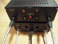
Dirk, it certainly looks like an impeccable installation, congrats!
What volume control are you using here?
MFG
Claude
What volume control are you using here?
MFG
Claude
Looks great Dirk, that's a lot of matching. 🙂 I ordered extra to do a little matching myself, but not as much as you.
to ClaudeG #1947
Hello Claude,
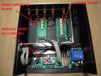
the PCBs for the input and volume control are sold from a german DIYaudioshop (it is not my work!).
It is based on an ARDU..O Na.o as controller. The sketch / programm is freely
downloadable.
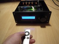
You can add a display and IR-control/remote ( I used an Ap..e remote).
I send you a pm.
Greets
Dirk
Hello Claude,
the PCBs for the input and volume control are sold from a german DIYaudioshop (it is not my work!).
It is based on an ARDU..O Na.o as controller. The sketch / programm is freely
downloadable.
You can add a display and IR-control/remote ( I used an Ap..e remote).
I send you a pm.
Greets
Dirk

Here is a possibly dumb question -
I am finishing up building this project - the preamp board is built and tested, and the power supply is also built and tested. I am waiting for the switches and RCA jacks to finish the wiring.
Q - Should the power supply ground- a Tubecad dual regulated, 18 volt supply, be connected to the chassis ground with a thermistor? I think so, but want to be sure. That is how I built the F6 - with the help of 6L6's build guide.
Thanks in advance,
bmdduck
Hi all...
Is it overkill using a highly regulated power supply such as Belleson super regulators on the rails...
Or would lm317 and lm337 work just as well...
Thanks
Is it overkill using a highly regulated power supply such as Belleson super regulators on the rails...
Or would lm317 and lm337 work just as well...
Thanks
I completed both of my boards for balanced operation with both boards having the jumper by P1 installed to connect the grounds between the boards. I was able to adjust offset on all four sections with no drama.
I spent last night re-reading the thread before I start wiring the boards to the enclosure. On post #1058, the XLR connector has pin 2 to IN +, and pin 1 to ground, with the ground jumper-ed to IN -.
Pin 3 of the XLR goes to the other side of the board to IN -, and pin 1 to ground and jumper-ed to IN +.
On post #1078, XLR pin 2 to IN +, pin 1 to ground and jumper-ed to IN -. Pin 3 to IN + on the other side of the board with pin 1 to ground and jumper-ed to IN -.
Now I'm very confused since they don't match each other.
I was going to wire the XLR pin 2 to IN + and pin 3 to the other side IN - with pin 1 to ground and then jumper-ed to either IN + or IN -.
What is the correct way to wire an XLR connector to the inputs?
Hi all...
Is it overkill using a highly regulated power supply such as Belleson super regulators on the rails...
Or would lm317 and lm337 work just as well...
Thanks
for my ears, decent shunt reg is always superior to decent series reg
but, that's me
I completed both of my boards for balanced operation with both boards having the jumper by P1 installed to connect the grounds between the boards. I was able to adjust offset on all four sections with no drama.
I spent last night re-reading the thread before I start wiring the boards to the enclosure. On post #1058, the XLR connector has pin 2 to IN +, and pin 1 to ground, with the ground jumper-ed to IN -.
Pin 3 of the XLR goes to the other side of the board to IN -, and pin 1 to ground and jumper-ed to IN +.
On post #1078, XLR pin 2 to IN +, pin 1 to ground and jumper-ed to IN -. Pin 3 to IN + on the other side of the board with pin 1 to ground and jumper-ed to IN -.
Now I'm very confused since they don't match each other.
I was going to wire the XLR pin 2 to IN + and pin 3 to the other side IN - with pin 1 to ground and then jumper-ed to either IN + or IN -.
What is the correct way to wire an XLR connector to the inputs?
pin 1 is always GND
pin 2 is always positive phase
pin 3 is always negative phase
sole choice you have thre is - to connect pin 1 to chassis, or to GND on pcb
chassis connection is more by standards
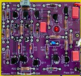
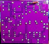
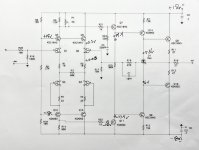
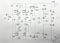
I built up a pair of the original purple boards and listened happily for a few months. Then one board stopped working. Since I had slightly butchered it by lifting some traces while trying to R&R a transistor I had installed backwards, I decided to build up another board, as I had extra PCBs and parts.
The second board never worked. I've inspected everything over and over, and have looked for mistakes, but I can't see anything. The board that works draws 30mA per rail, it is easy to balance the DC out, and the LED is brightly lit. On the board that doesn't work, the rails draw 18mA each, the DC offset never gets below 6v and the LED is dimly lit. I figured with one working board, I should be able to figure out what was wrong with the other board, but that has not proven to be the case.
I could build up another board, but at this point I think I'd rather learn something. So I am asking for some troubleshooting help. What should I measure to find the problem, and why?
I have included four images. Two show the front and back of the non-working board. and the other two show DC voltage measurements of the good and bad boards.
Any help appreciated. Thank you.
Attachments
- Home
- Amplifiers
- Pass Labs
- Wayne's BA 2018 linestage