Where are these recommendations coming from? I bought the parts kit from DiyAudioStore and wasn't aware it was already out of fashion!
They are on a schematic posted by 6L6 with the notes on. This was posted earlier on in this thread and I believe they were included in the kit.
I followed the notes I had. There's more changes too like a couple of resistors to change. Take a look at the notes in the pic. You should use the 15R resistors with the bigger output transistors for maximum bias.
I caught the resistor change and have used 15ohm 0.5W in positions R11, R12, R32 and R33. Guess I missed the note about leaving C4/C9 and R23/R46 open. Thanks for the heads up.
Big lesson for me (well, biggest so far) is to make sure I order everything in one go. This must be the third order from Mouser for this pre-amp.
Yes, it took me about 5 rounds to get good at Mouser, there was always one part which was missing no matter how careful I thought I was.
My approach now is this: Mouser lets you define a "project". These look just like a shopping basket (including final price); putting it into a project lets you get all the parts for one item into one place. Really helps if you are trying to get the right part count for 2 or more items.
Once you project list checks out, you can hit "order project" to put it in the shopping basket.
- Make a new project call it i.e. "Waynes Linestage".
- Put all of the parts you'll need into that project. I
- Print out the project list and double-check against your planning docs.
- Double-check your planning docs against reality.
- Repeat until convergence
- Order project
This way, if you are ordering for two projects, you don't have to remember how many of the caps were for the linestage and how many were for the PSU...
My last 4 or 5 mouser order have worked perfectly (no missed parts), and most of these were for multiple boards/projects.
Hopefully by the end of next week it'll be making music and not smoke.
Beautiful work on the solder joints. It is going to sound great when finished.
They are on a schematic posted by 6L6 with the notes on. This was posted earlier on in this thread and I believe they were included in the kit.
Hey, thanks for pointing this out. Yes, the notes are included on the schematic in the kit I bought from DIY audio, also in the schematic linked from the store website
HOWEVER== the notes were a little confusing to me. I thought they applied only if you were using the "alternate output devices" transistors.
thanks for clarifying.
My last 4 or 5 mouser order have worked perfectly (no missed parts), and most of these were for multiple boards/projects.
Another good trick is to use the possibility to add your own number to the parts, for example „W18 R1 R2 R3“ which will be present on the bag‘s sticker. Much easier to sort out the parts when building has started...
Thanks guys for the tips on being able to set up “projects” on mouser’s website. And especially the ability to add references to individual parts. This should save an awful lot of unnecessary re-orders in the future.
Beautiful work on the solder joints. It is going to sound great when finished.
Thanks for the compliment. I try to make sure I clean the boards thoroughly with isopropyl alcohol before I begin. And also clean the component leads where possible so they are shiny and clean before soldering everything. A bit of a time consuming process but seems to help give nice clean soldered joints first time.
I'm still trying to wrap my head around how a "consumer" audio system works, forgive the newbie questions... but as I want my linestage to gracefully handle several different input levels, I want a crystal-clear and completely explicit understanding of the function/purpose of the preamp.
The "pre-amp":
As I understand it, the input signal(s) enter through a set of jacks/terminals/etc. They would then normally go to a selector switch, which would route one signal on to the volume control and the rest to ground. (more precisely, each input has a left positive, a right positive, and a ground channel. Ground always goes to ground, the selected left/right positive channels would pass through the selector switch to the volume control. The non-selected left/right positive channels route to ground or are left as an open circuit. And we forget about the special challenges of phono inputs)
Let's assume the volume control is based on a pot (or one pot per channel, possible with other resistive devices in the signal path) while noting that other solutions are possible. The pot is wired as a voltage divider, sending a portion of the input to the linestage and the rest to ground.
The linestage takes the input from the volume control and applies a fixed gain factor to it. The linestage can expect to drive a load with a fixed impedance; it's main design challenge is fast response/low-distortion amplification across a wide frequency range.
the "power amp" and downstream
The output of the linestage goes into the power amp, which presents a fixed input impedance and applies a fixed gain to its input. The primary design challenge is maintaining distortion-free amplification against the signal- and frequency-dependent impedance of the load.
Don't want to go down the rabbit hole of monoblock amp setups, crossover networks, and other goodies-- Let's just call everything downstream of the linestage/preamp the "the power amp" for now, as my concern is the preamp.
Is that basically it?
My situation:
I want to switch between (all input voltages approximate and device/ device output volume setting/ dependent):
And I'm wondering if I would want to add some kind of balancer between the input and selector switch, so that the output of the switch does not depend on the input device (i.e. a voltage divider to take down the synth's output, and maybe a small chip op-amp to bump up the smartphone input).
The synth is my main concern. It expects 100KOhm input impedance, which is easy enough to add to the switch wiring if I think about it. OTOH, I've been running the synth into the headphone jack of my store-bought amplifier (combined pre-amp and amp in one box) w/o problem for years, as long as I keep the volume knob below 3, and it can also feed into a desktop computer sound card w/o problem.
The "pre-amp":
As I understand it, the input signal(s) enter through a set of jacks/terminals/etc. They would then normally go to a selector switch, which would route one signal on to the volume control and the rest to ground. (more precisely, each input has a left positive, a right positive, and a ground channel. Ground always goes to ground, the selected left/right positive channels would pass through the selector switch to the volume control. The non-selected left/right positive channels route to ground or are left as an open circuit. And we forget about the special challenges of phono inputs)
Let's assume the volume control is based on a pot (or one pot per channel, possible with other resistive devices in the signal path) while noting that other solutions are possible. The pot is wired as a voltage divider, sending a portion of the input to the linestage and the rest to ground.
The linestage takes the input from the volume control and applies a fixed gain factor to it. The linestage can expect to drive a load with a fixed impedance; it's main design challenge is fast response/low-distortion amplification across a wide frequency range.
the "power amp" and downstream
The output of the linestage goes into the power amp, which presents a fixed input impedance and applies a fixed gain to its input. The primary design challenge is maintaining distortion-free amplification against the signal- and frequency-dependent impedance of the load.
Don't want to go down the rabbit hole of monoblock amp setups, crossover networks, and other goodies-- Let's just call everything downstream of the linestage/preamp the "the power amp" for now, as my concern is the preamp.
Is that basically it?
My situation:
I want to switch between (all input voltages approximate and device/ device output volume setting/ dependent):
- normal line-level inputs (from consumer audio devices via RCA jacks, expected input +/- 1.7V) [I think. Corrections welcome],
- a smartphone input (3.5mm stereo plug, expected input 0-0.5V)[I think. Corrections welcome],
- a synthesizer input (3.5mm stereo plug, expected input +/- 10V)
And I'm wondering if I would want to add some kind of balancer between the input and selector switch, so that the output of the switch does not depend on the input device (i.e. a voltage divider to take down the synth's output, and maybe a small chip op-amp to bump up the smartphone input).
The synth is my main concern. It expects 100KOhm input impedance, which is easy enough to add to the switch wiring if I think about it. OTOH, I've been running the synth into the headphone jack of my store-bought amplifier (combined pre-amp and amp in one box) w/o problem for years, as long as I keep the volume knob below 3, and it can also feed into a desktop computer sound card w/o problem.
Instead of custom building a preamp to suit your unique needs I would consider making inline attenuators for the synth input.
Inline attenuators are simple. You can buy them ready made, or you can make your own (much cheaper). For each channel (R/L) you would have one female RCA socket, one male RCA socket, and 2 resistors. Construct them into a small tube/barrel and then you can put them between your source and preamp where needed.
The off the shelf inline attenuators (€€€) look like:

Here's the circuit (simple):
Here's an article showing how to build them:
Homemade RCA Attenuator : 5 Steps (with Pictures) - Instructables
This should be a more flexible, modular option than tailoring the various preamp inputs.
Inline attenuators are simple. You can buy them ready made, or you can make your own (much cheaper). For each channel (R/L) you would have one female RCA socket, one male RCA socket, and 2 resistors. Construct them into a small tube/barrel and then you can put them between your source and preamp where needed.
The off the shelf inline attenuators (€€€) look like:
Here's the circuit (simple):
Here's an article showing how to build them:
Homemade RCA Attenuator : 5 Steps (with Pictures) - Instructables
This should be a more flexible, modular option than tailoring the various preamp inputs.
Last edited:
Instead of custom building a preamp to suit your unique needs I would consider making inline attenuators for the synth input.
This should be a more flexible, modular option than tailoring the various preamp inputs.
Yes, I see the wisdom in your proposal. Thanks.
It's finally finished and it's sounds phenomenal!!! Just got the volume knob to change then I'm happy. Really pleased with how my own power supply performs too. It's super quiet! 🙂
Attachments
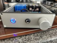
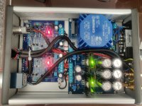
Here is my version of the BA2018 based on the purple boards, right now using bluetac to hold the boards. Running with Silent Switcher using a mobile adapter and using the +/-15v. Works perfectly with a 50k TKD pot lots of gain and easily powers my HD598 headphones 🙂

Here is my version of the BA2018 based on the purple boards, right now using bluetac to hold the boards. Running with Silent Switcher using a mobile adapter and using the +/-15v. Works perfectly with a 50k TKD pot lots of gain and easily powers my HD598 headphones 🙂
https://ibb.co/r0Pc5Kv
Nice looking build you got there! I used 50K for my pot too but I find the gain lower compared to the whammy as I have to turn the volume up half way to get to my usual listening level. Overall it's awesome! 🙂
Thanks, this is simple DIY chassis from aliexpress which I got long back. Using some drill bit I could make some RCA holes and DC jack hole and the front panel pot. I found it to be clinical with good highs and deep sound stage. Playing Roon core and Pi as transport to my Soekris DAC its very good 🙂
Wonderful!! Nicely done!! 🙂 🙂 🙂
Silent Switcher is a great option for this circuit.
Yes Jim with a +/-15v the BA runs with so much gain and I can hardly think going above can easily drive any power amp.
connecting the pot
Nice build...what kind of connectors are you using with the TKD pot ? I usually end up with some fiddly soldering. They are nice pots...I use the smaller stepped one which has a nice feel and sounds as good as I can tell
Nice build...what kind of connectors are you using with the TKD pot ? I usually end up with some fiddly soldering. They are nice pots...I use the smaller stepped one which has a nice feel and sounds as good as I can tell
Does anyone know what the current draw is for the build with the larger output devices. Earlier in the thread the base build was shown as 60 mA per channel, I wondering if I need to beef up my psu if I go with the other outputs.
Too much PS current availability doesn’t hurt.
I had measured this earlier. With the beefier outputs, it’s actually about 40mA/ch at idle.
I would aim for a PS that can cleanly provide 100mA (minimum)... this should suffice the idle current and light loads and nominal listening levels (assuming headphones). Understand a 600 ohm load can increase current requirements dramatically, like 50mA.
It really depends on how often you are driving the preamp to clipping (just at idle) and then adding the load on top of that.
The SilentSwitcher V3, provides +/- 15VDC and 150mA which is very good for this circuit.
Best,
Anand.
Last edited:
- Home
- Amplifiers
- Pass Labs
- Wayne's BA 2018 linestage