Donovas - if things are working properly at 13v, there’s no reason to adjust! 🙂
Enjoy the music!
Enjoy the music!
Thank you but... i want it running hotter! The current draw is really small and i can definitely feel how 'soft' the drive is compared to my higher biased circuits
The UFSP phono preamp by Salas is integrated into the enclosure of the BA2018 preamp, the sound of this phono stage is far superior to the FSP and Threshold FET 10Pe phono preamps I own.
Elwood, I was thinking of doing something similar. What size is your chassis? Could you post some photos?
Thanks!
The psu is good enough! Adjusted it to -+18v and felt that it still wasnt running warm enough. What i will do next is lower the most of the ccs resistor values to 1/5th of what it is now, leaving the resistors around the jfet and the 1k resistors untouched. And then try again at 13v
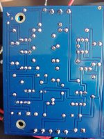
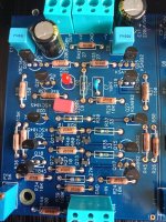
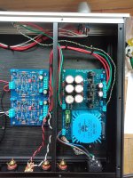
Here is the build btw. Its lclc filter feeding cascoded lm317/337 then wayne's preamp modules that i did the layout for from the schematic. Its dead silent. You could hook it up to an iem and still not hear any hum.
Not happy with the module's layout tho. I will make it tighter next time 😀
Not happy with the module's layout tho. I will make it tighter next time 😀
Attachments


Oh! Very nice indeed. I thought your PSU could only make +/-13v. There’s no question in my mind that the BA2018 likes the higher voltages, 18-20v seems to be the sweet spot, but I have one running at 15v that sounds wonderful as well.
Oh! Very nice indeed. I thought your PSU could only make +/-13v. There’s no question in my mind that the BA2018 likes the higher voltages, 18-20v seems to be the sweet spot, but I have one running at 15v that sounds wonderful as well.
I, too, am using +-15V. I note that earlier a mention was made of an Academy Audio recommended resistor change to move the "sweet spot" from 18V to 15V. Is this a Wayne-approved modification that actually keeps the board performing at optimum?
Wayne “approved” the PCB to run from 15-24V.
The resistor change to keep the current similar at slightly lower voltage is from the Academy Audio app note as mentioned, (which is excellent, BTW…) and is a fine idea.
The resistor change to keep the current similar at slightly lower voltage is from the Academy Audio app note as mentioned, (which is excellent, BTW…) and is a fine idea.
Wayne “approved” the PCB to run from 15-24V.
The resistor change to keep the current similar at slightly lower voltage is from the Academy Audio app note as mentioned, (which is excellent, BTW…) and is a fine idea.
Sorry I was a little obscure -- what I really want to know is, does the change of resistor value make any audible difference when running the board at the 15-volt end of the voltage range? I need to decide whether to replace the resistors or not . . .
Thanks 6L6
I got the bias tuned. Changes were 10k ohms> 100ohm, 27k>1k5 and changed the led to 2k trimpot. I have the outputs dialed at 700ma and all the transistors are nice and warm at -+13v (smile)
The sound is very dynamic and open now. However more transistor-y than before? Did i lower the psrr with my changes? Or is the 2k trimpot noisier than the led?
I was expecting the 100k ohm to be the bias resistor and the bjts after that being driver transistors. Was the working of this circuit ever explained somewhere? As appreciate as i am i dont have the time to read all 300 pages of this thread this weekend 🙁
Last edited by a moderator:
Wapo - try it and find out! What’s the worst that happens, you change a couple resistors.
Speaking in broad generalities, more standing current usually sounds better.
Speaking in broad generalities, more standing current usually sounds better.
Thanks 6L6
I got the bias tuned. Changes were 10k ohms> 100ohm, 27k>1k5 and changed the led to 2k trimpot. I have the outputs dialed at 700ma and all the transistors are nice and warm at -+13v (smile)
.......
700mA!?!
care to clarify that?
Was the working of this circuit ever explained somewhere?
Yes. It’s quite simply a discrete opamp.
If you haven't seen this, you should watch it. Burning Amp 2018 Colburn Final - YouTube
Last edited:
Wapo - try it and find out! What’s the worst that happens, you change a couple resistors.
As in, "reinvent the wheel for the fun of it?"
The worst that can happen, while unlikely, is way worse than replacing a couple of resistors and to do the job properly involves more than just soldering the resistors.
It sounds like the change, if it exists, is too subtle for anyone to have a definitive answer. I do like the sound as-is at 15 volts and original resistor values, so lacking clear recommendation to the contrary I'll stay where I am.
700mA!?!
care to clarify that?
Measured it across the 10ohm emitter resistor. Since then ive dialed it down to 300ma. The resistors were getting too hot!
And thank you again 6L6. Definitely watching that vid
Last edited by a moderator:
As in, "reinvent the wheel for the fun of it?"
Lol…not at all.
It sounds like the change, if it exists, is too subtle for anyone to have a definitive answer.
I suspect it’s been done only once or twice. Like I said earlier, it’s a fine idea and more current typically sounds better.
As for “definitive”, this being DIY, you are encouraged to give it a try and find out yourself, and it’s always appreciated to share your findings here. You’ll rarely find people here who will tell you exactly what to do, as there is no ‘right’ answer, rather to try things and see what works for you. That’s why you will very, very rarely find clear recommendations to small tweaks like this.
I personally, at 15v, would try it.
Bubba177 (or anyone else),
Here are some photos of my build, including the power supply.
I posted a few posts back (2999), hoping for some insight into a problem I'm having with my recent build - wondering if anyone has any idea what's gone wrong?
Any help appreciated!
Here are some photos of my build, including the power supply.
I posted a few posts back (2999), hoping for some insight into a problem I'm having with my recent build - wondering if anyone has any idea what's gone wrong?
Any help appreciated!
Attachments
I had similar issues to you. I reflowed the SMD Jfets and then had different issues...
Not wanting to put the work into using the old parts again, I put some new ones in there, had a lot of DC offset, 17 volts worth, then floating one more time and it worked. Was able to set DC offset properly. Had sound, good center image etc.
One of the times when I was having these issues, one of them was even microphonic. Could have been a loose connection.
These little SMD chips are cheap. I would say order a bunch from Mouser or digikey so you have a bunch from the same batch and give it another shot.
- Home
- Amplifiers
- Pass Labs
- Wayne's BA 2018 linestage